UPDATED - CORRECTIONS AND ADDITIONS
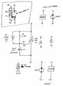
Okay, let me see if I can make this make sense. I've uploaded a schematic to my gallery:
Danger Danger Will Robinson: electronics ahead!

Any electronics store should have all these components - I have a salvage electronics store down the road that would have all this for about $2.00.
The key is the SCR, which is a sort of double transistor switch that stays off until a small voltage is applied to its gate terminal, when it "fires" and closes like a switch. It will stay closed, conducting electricity, until power is removed.
If you put this in line with a buzzer or lamp, the lamp will stay off until the sensor switch closes. Then the capacitor will slowly charge through the 2.2M resistor until it reaches the voltage to trigger the SCR's gate. The SCR closes and the buzzer or lamp goes off until you kill the power.
If you use an SCR in a TO-3 case (see illustration), you can build this as a "wireframe" circuit with no circuit board and put it in a small tube of some kind.
If the sensor switch connects to ground when it activates (as do most low-pressure switches) use circuit A - run switched 12 volt to the buzzer and put the circuit between the buzzer and ground. If the sensor connects to +12V when it activates, use circuit B - ground the buzzer and run +12V from the sensor to the circuit.
When the sensor closes, the circuit starts charging. If the sensor opens again before about 2 seconds, nothing will happen. Once it goes over the 2 second mark, the circuit will "fire" and the buzzer will sound or lamp will light. The buzzer/lamp will stay on until the sensor switch opens or until you kill switched +12V.
It's best to test it a few times before putting it in a tube or installing it. If the delay is too long, make the 2.2M resistor a little smaller - 1.8M, 1.5M, even 1.0M. If it's too short, increase the resistor in similar steps until you have about a 2 second delay or whatever suits you.
The good: it's cheap and works well. The bad: you do need a tiny bit of electronics assembly ability to build it right.
I've updated the diagram to show where the sensor switch goes in each circuit - the circuit will trigger when the sensor switch closes (typical automotive sensor behavior). I also corrected a small error - I suggest a TO-220 case, not a T)-3 - and added a small diagram showing how to build this circuit "flat" with no circuit board. Once built and tested, you can glue the circuit to a square of plastic and cover it with shrinkwrap, tape or a tube.