To continue this project I read everything I could on the subject, including: Jim Miller's articles, his patent, some engineering articles that mention Milller's mid-lift method and hours of reading various forums. I also called two major companies that sell rockers. To be honest I was disappointed in all of it. I was hoping to find something with some testing and results. I found nothing but stated conclusions based on beliefs and not supported by testing and results. It may be somewhere but I couldn't find it.
I, like many others, have been building engines on and off since the mid-sixties, mostly as a hobby, but at many times to make extra money. I had four years of formal auto shop training and lived for it but I never got into the geometry of the rocker arms other than switching out some 1.5s for 1.6s. I have been degreeing cams in for about twenty five plus years but just never thought that all that work on cam design could be negated by a bad rocker design. Who would have thought a 1.6 rocker may not produce close to 1.6 of cam lift?
Lacking some testing results other than the second video above I decided to do some testing of my own. I wanted to see what was really happening at the valve. Now I know why the cam companies call it theoretical lift. After talking with Scorpion, I realized there had to be a method to get an idea of what was happening without buying tons of rockers so I decided to start with three rockers a lot of us have; a stock pedestal rocker, a Comp Cams Magnum and a stock old style cast steel sixties/seventies rocker; all 1.6 ratio.
TESTING METHOD
I tested the rockers on a mild built spare roller 5.0 engine I just finished building. It has a Comp Extreme Energy cam #35-320-8 with Ford Racing Roller lifters. The heads are fully ported cast iron E7s with Trick Flow springs and retainers. The cam had been degreed in and was overall pretty good. The lift was checked at the cam and was within a couple thousands.
An old lifter was taken apart, the valve and spring removed. The lower piston turned upside down and shims added so it was solid but approx. .035 down from the clip to simulate actual pre-load running conditions. Since this has a lot to do with pushrod length this is critical to do a running set-up, not just adding the pre-load measurement later. This cannot be done accurately with a stock pumped up lifter as they will bleed down in the middle of testing.
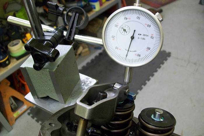
The degree wheel was set up and TDC'd on the crank. The degree wheel was marked at .006 start of intake lift and every 20 degrees of crank rotation, the lobe center and ½ lift positions were also marked and the .006 valve closed point. An adjustable pushrod was used. A 1 dial indicator was set-up on the valve retainer, inline with the valve movement.
In doing research I found that there are actually two variations of the mid-lift method. The one in the first video that is based on the theoretical gross valve lift and Millers method, based on the net cam lift measured from the stem side roller center to the fulcrum center less ½ net lift. Meaning the center of the fulcrum less ½ the net lift measured at 90 degrees to the valve stem. In this case, the center point of the fulcrum needed to be .160 based on .320 cam lift, below the center of the valve stem side roller tip, or if there is no roller, the shoe or sled surface of the rocker to the center fulcrum roller or center pivot point. The Miller method is more difficult to measure but there is no tightening the rocker bolt and counting the turns in this process. You use the adjustable pushrod to raise or lower to the proper rocker height and then measure the pushrod length.
I completed seven tests measuring and recording at each 20 degree crank rotation plus the ½ lift and actual gross lift points. I tested all three rockers with a stock pushrod. I tested the Comp Cams and the old cast steel rocker using the ½ gross lift method. I tested those two again using the ½ lift net method.
One thing I realized during the testing is that the gross lift is an in-the-ballpark test because the gross valve may not be correct from the start. So, starting from that theoretical gross valve lift figure is highly suspect.
The results will have to be in another post as I am trying to figure a good method to present them. Let me just say I had no idea and was shocked.