Measured for pushrod length, checked the rocker arm pattern on the valve stem (no changes were necessary), and torqued the heads down......then retorqued the next day.
Oil pump and pickup were bolted on.
Bead blasted a C3 factory timing cover and found a crack. Figures.
Intake manifold gaskets were glued to the head with TA-31 around the ports and water jackets. Intake manifold was test fitted....
Here's the fun part. I'd like to sit down with the engineer who designed the FE intake setup....maybe put my arm around him....tightly....and explain a few things to him.

I first put the intake on without gaskets and check the angles. Chris' intake is a Performer RPM and the angles look great: the intake fits nice and flush against the cylinder head.
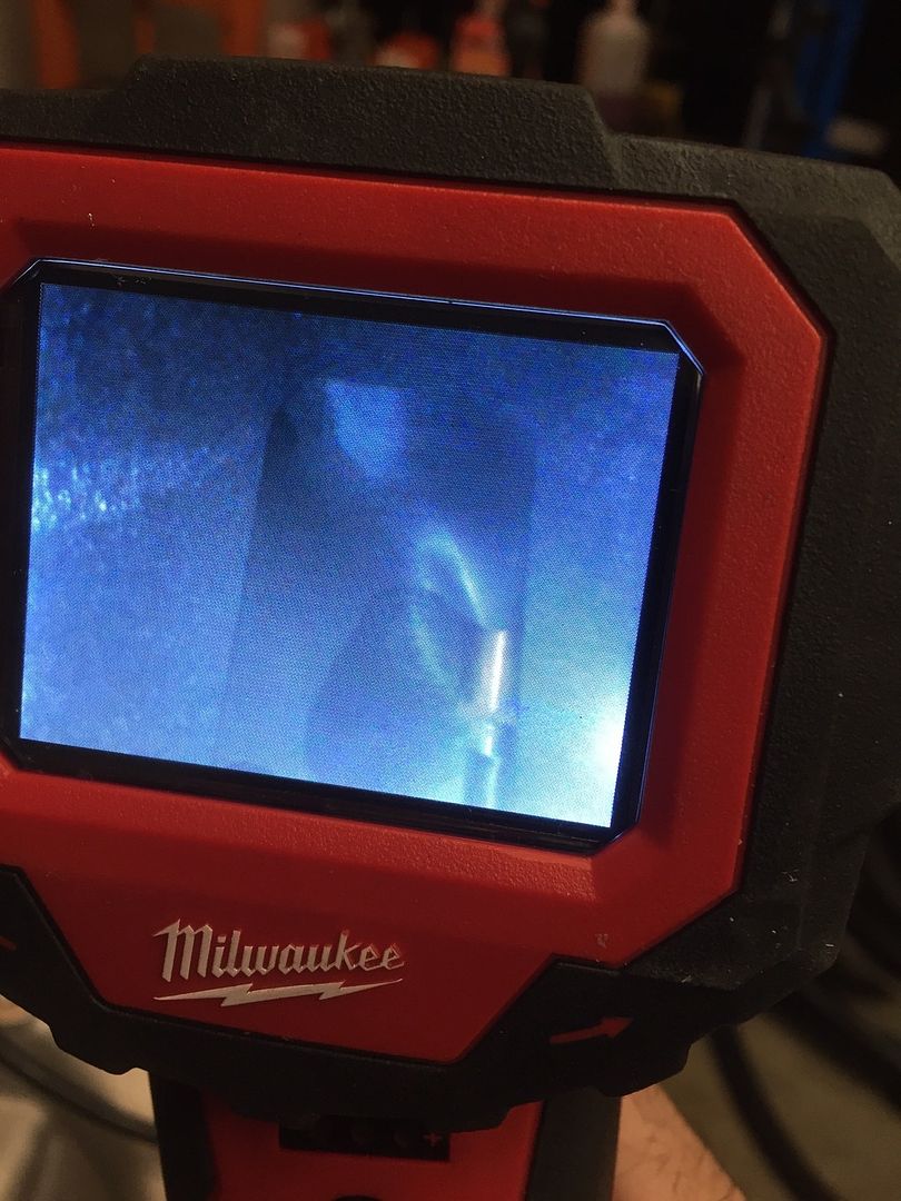
Checked port alignment with a borescope:

Everything looks great there, the roof of the intake runner is maybe .010" below the roof of the head port and the sides line up great.
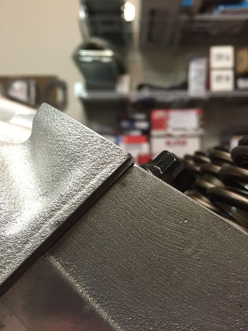
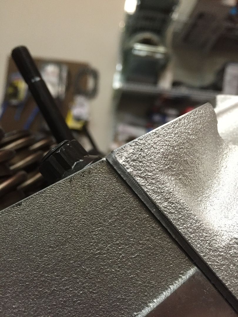
Once that is established and it's decided that the flanges don't need to be cut, I look at the valve cover rails:


Can't have that....
So, the valve cover flanges on the intake will need to be milled: about .020" on the passenger side and about .050" on the driver's side. That will insure the valve cover flange is flat, even, and the seal will be tight.