Steve, the "classic" protocol for diagnosing the old style alternator, external VR, and charging light (whether you have an ammeter as well or not) is to jumper the VR to force the alternator to output a higher voltage. First, make absolutely sure you've got 12v going to the "A" connector of the voltage regulator. Then, if you run a jumper wire between the 12v power at "A" and the "F" connector on the voltage regulator, and then start the car with the engine running no faster than 1500 RPM, the ammeter should show a charge and the voltage should be 14 volts or higher. If that happens, then the voltage regulator is either bad or it is not getting excited from the idiot light. On the other hand, if you still have no charging then the problem is that the alternator has failed or you have a broken charging wire or broken wires between the VR and the alternator. You can do this jumpering test with the plug pulled off of the VR so that it is totally disconnected.
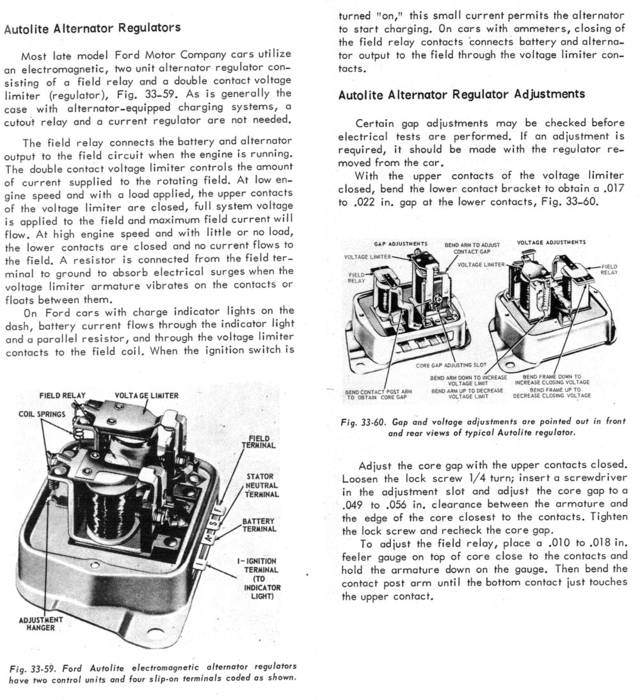
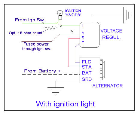
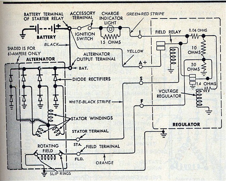
Below are three pics. The first is a blurb from my auto shop manual, circa 1975, explaining the idiot light's role in exciting the charging system in Ford cars. The second pic is just a very simple drawing that ERA likes to use to explain the wiring and the need, sometimes, for the extra 15 ohm resistor. The third pic is the original Ford schematic. On the internet forums you will find a lot of differing advice as to the resistance level needed to excite the VR. Some say 500 ohms, some say 15 ohms. Different VRs (original, new solid state, etc.) will respond to different levels of current. If you do find, for some reason, that the light that used to excite the VR is no longer doing its job, then, if you add a parallel resistor, you must have a 20 watt or greater rating on that 15 ohm resistor, or it will eventually burn up. One possible scenario that I have seen (OK, on the forums, not with my own two eyes) is an undersized parallel resistor that worked fine for a couple of years and then burned up. The idiot light would then come on, the alternator tested good, the voltage regulator tested good, but the system wouldn't charge properly until a new resistor was added in (with a higher wattage so it didn't burn up). This stuff is not rocket science -- you've only got a couple of components and the wires in between. It's really pretty easy -- once you've done it a couple of times you can usually find the glitch in about ten minutes.