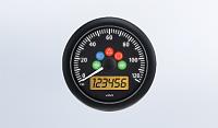
Well Iím working my way down my punch list of the minor things to finish up on my build. The Cobra has been roadworthy for nearly a year with close to 800 miles and 75 hours of FUN-TIME. This weeks priority was getting my VDO Speedometer calibrated and programmed. The process is similar for many brands of programmable Speedos but this was my first ever. Hope this Tech Tip can save the next guy a few hours. Iím using the Viewline series of VDO gauges in my dash. The Speedo part number is A2C53408268-S. It uses telltale lights built in for turn signals/hazards , e-brake light, high beam and speed alarm. It saved me space on my dash.

Iím using a TKO600 Ford tranny that comes equipped with a Ford VSS (inductive sender). These are 2 pin sensors that do not require a voltage input, they create a voltage pulse output signal ( inductive) I had to purchase the pig tale connector to connect the VSS using a Standard Motor Product s part # HP 4475
Standard Motor Products HP4475 Speed Sensor pigtail connector available here:
https://www.amazon.com/dp/B006X0CYDW...ing=UTF8&psc=1
Following the VDO instructions of course left me unimpressed even after watching their You Tube videos. Here are the instructions provided.
https://www.vdo-instruments.com/medi...les%2085mm.pdf
VDO states there are 3 main ways to provide input signal to the Speedo; Hall Effect, Inductive, GPS or vehicle ECU output which may need to be conditioned before entering the speedo. I used the cheap and reliable Ford Inductive VSS
The two wires from the VSS connect directly to the two signal pins on the Speedo. One pin is an internal ref Ground and the other the input pulse voltage using the inductive type sensor.
Lessons Learned
No matter how many times I tried the Auto Calibration method described by VDO using my inductive sensor, the speedo counted to 7,295 pulses which was not correct for a measured mile. Knowing this Ford VSS generates 12 pulses/ driveshaft revolution (very important) allows me to calculate total pulses expected from VSS after a measured mile. See the simple math here:
325/50/15 tire has 747 revs per mile
Ford Sensors have 12 pulses/ driveshaft revolution
Using 3.25:1 axle ratio;
12x3.25 = 39 pulses of driveshaft per 1 tire revolution.
747x 39= 29,133 pulses per mile!! Theoretical : But the tire under load installed at 30 psi is a little smaller in dia.
Driving the car in my measured mile multiple times while in AUTO-CALIBRATE mode continued to count only 7,295 pulses. This is about 25% (7295x 4= 29,180) of what it should be. If someone reading this is more experienced with this Speedo , please PM me why this happened repeatedly. ???? Iím lost! I abandoned the auto calibrate method and manually entered the correct theoretical 29,133 pulses. Now the speedo works perfectly and agrees with various iPhone apps for speed within 1.0 mph. Problem solved!
VSS Reference Info here: