Hello again all,
So another catch up / update for you. A bit of a long one……..
After the cowl tube rework and pedal box fixes I wanted to keep moving forward. I wanted to deal with the floor but that means I need the seat rails and although I think I know what I am using there I really wanted the seats on hand to test the fit of everything and make decisions.
There are a lot of drawing notes from Chuck that go something like “ spacing to be determined by part used……” or something like that basically I need the parts to be sure they fit. So I ordered some seats and of course need to wait for them.

I still need to do everything else so what next, I turned my gaze to the rear end area.
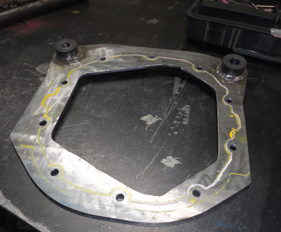
I have the diff mounts finished so what about the diff?
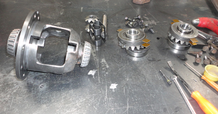
After my parts gathering and the kindness of friends I have four 8.8 differentials at hand, 3 IRS units and one straight axle with a trac-lok from the mustang that gave its engine and transmission for the build.
One of the IRS units is the alloy case currently in the chassis that had 2.73 gears and an open diff from a Lincoln, another one has an iron case, 3.08 gears and an open diff from the Cougar and the final one has the iron case, 2.73 gears and a trac-lok diff from a friend at work.
A nice collection of parts but what I want is the 3.08 with a trac-lok in IRS form. I am no expert on these things and don’t possess the fancy tools to check and shim these units but I had an idea….
So I started with the 2.73 trac-lok unit and took it apart, and cleaned it, keeping everything sorted out for later.
I discovered the friction packs were not worn out too badly but they were missing some of the tabs on the clutch plates so I need to fix that.
The best deal I found was actually an OEM Ford set on Amazon, go figure

, and it was much cheaper than a budget Dorman branded set from a parts place…hmmmm…go figure that too.
These are obviously an upgrade as the tabs on the clutch plates are now rounded and there is a different stack up recommended with the plates and drive disks, the kit even included the Ford friction modifier for the
oil, nice stuff!
So with the Trac-lok back together I disassembled the 3.08 IRS unit enough to remove the diff and its bearings and shims keeping track of everything’s location. I swapped the 3.08 ring onto the trac-lok diff and used the track-lok diff’s bearings and the shims from the 3.08 diff setup and bolted things back together.
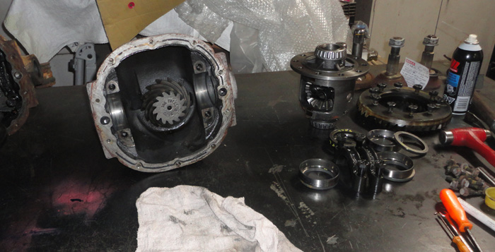
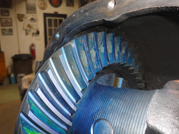
I put some layout blue on the ring and gave it a spin to check the pattern and used my dial indicator to check the backlash, I checked before I took things apart too.
You really need to love mass production and modern machining, the specs I have call for .008 to .012 backlash. When I checked the 3.08 set before I removed it, it was at .009, with the Trac-lok and its bearings in place of the open diff the backlash is now .010”, thanks Ford!
I am happy with that, I am not going to try and change it, it is within the range and the pattern looks good too.
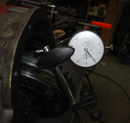
I did not disturb the pinion in the case so that depth is still the same and it’s the same ring gear back in the same case too, so I think this might be a win

I also added a drain hole to the bottom of the case, threaded to use one of the OEM magnetic plugs I have.
In the end it seems the steel cover is my best choice so I made a bung and welded it in the correct location for filling the diff, it also features one of those OEM magnetic plugs too.
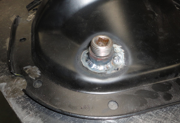
It was time to finish this up so I wanted to seal the mounting plate between the cover and the case, taking a cue from the factory alloy covers I ground a groove around the sealing area on both sides with a ( few) small diamond burr.
Then with everything super clean I applied orange adhesive sealant to both sides and torqued up the bolts. I painted the whole assembly with POR15 ( BTW it doesn’t stick to silicone
) and installed new seals and mounted it in the chassis. Fits perfectly and looks good to. Fingers crossed everything works in the end…..or rear end!
This all might be a bit long winded but I thought the explaining might help someone else down the road. I certainly spent a lot of time off and on worrying about how I was going to deal with the axles and such I just knew that at some point later I would need to.
Now about those axles

After much reading, thinking and head scratching I had an idea, apparently not an original idea ( I see you Mr. MAP ) but at the time I thought it was, but really is anything an original idea anymore?.
I had measured the original Cougar subframe setup with the adapters and wheels before I took it all apart, then when I had the new design suspension in I measured it again. The stock CV / tripod axles would need to be about 6 inches shorter on each side

. This did not leave much in the middle and a rather stumpy ugly end product.
I read horror stories of splined axles that had been shortened and re splined and then broke off, honestly most likely a case of too much power and poor/ no heat treating. I thought about doing an old school cut and shut with a sleeve or something, even just to get the correct length figured out so Mosher could make me some good ones later.
I found out someone was making 8.8 to Porsche 930 CV stub axles and got to thinking about making adapters of my own.
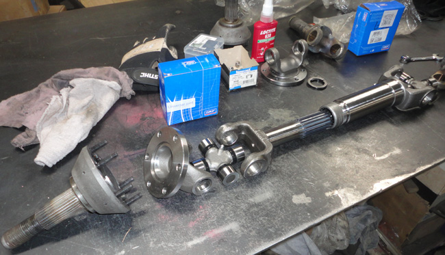
I found some posts on our site about the original Spicer(?) part numbers AC used and that got me looking at those parts. I had already picked up the yokes to build the driveshaft but there sure are a lot of different yokes, flanges and shafts available, wow!
I recognize the advantages of modern CV joints but the truth is even the mighty 427 Cobras and GT40’s had U joint, sliding spline type axles. Most Grand Prix cars of the 60’s did too, so if it was good enough for them….why not my car?
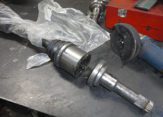
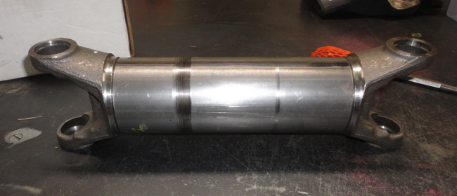
I took the old Cougar axles I had and sliced off the ends, lots of burning grease smoke and stink, but in the end a splined diff end with a retaining ring and a splined end with a nut for the hub.
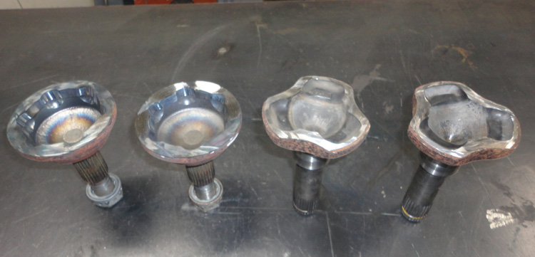
I thought about welding a plate to the inner and machining that for a flange but after I got to measuring and looking at the weld yokes for my drive shaft I figured I could machine the stub to fit a weld yoke and just skip the bolt on yoke part.
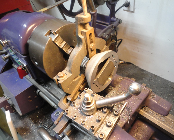
So I tried it out with my classic 1941 Logan lathe, the splined end will not fit in to the headstock all the way. This is the major short coming of the old Logan, the spindle hole is only just over ¾ inch but there are other ways to get this done. I cut off the excess material with a cut off wheel and I have a steady rest for the lathe so I used this to support the stub on the bearing / seal area with the stub as far into the chuck as I could. I just made light cuts and things seemed to go Ok.
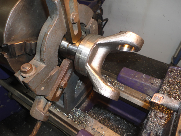
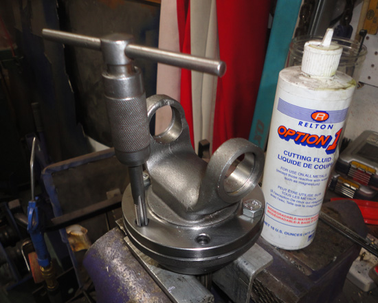
For the out board end I set the stub up the same way and tried to face cut it, wow that’s some hard stuff
, honestly I had suspected the CV joint would be hardened for wear resistance. So I annealed them by standing the hub in a pail of water up to the body of the CV to avoid to much heat transferring to the spline area just in case. Then heating the top surface to a nice orange/red color and just letting it cool slowly. Back into the lathe and yes now it can be machined a bit more easily.
So after I had a flat face I added a piece of ¼ steel into the open space and machined it along with the stub to leave a nice little step to center the excellent bolt on yoke I found, I believe it fits Toyota driveshafts but now it fits Ford CV bodies!
The yoke has six 8mm blot holes and the holes do line up very well with the thick areas of the CV between where the balls were so I could drill and tap these for some high strength studs.
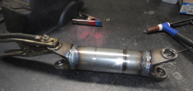
In the end I liked what I had done but did not really like the inner stub piece as the Cougar they came from had sat in somebody’s yard for years and there was a corroded area right where the seal contacted the axle, one side was worse than the other but I did not want to chance it and have an annoying little leak so I found a replacement set of axles ( pretty cheap too) and cut the inner stubs off.
It feels fairly strange to take a brand new axle half out of the bag and just lop the end off with a grinder and toss the rest, at least they were cheap.
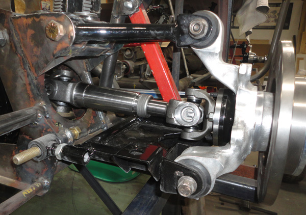
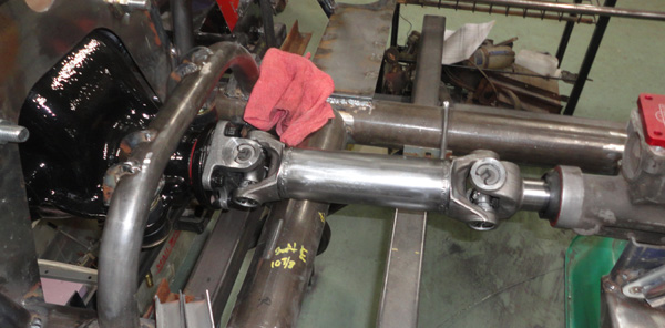
I machined the inners to fit the yokes and very carefully tig welded them together. The rest was fairly straight forward, assemble the U joints to the yoke parts slip the splines together and ta da! Axles! The best part was installing them; they fit like a glove and look great too!

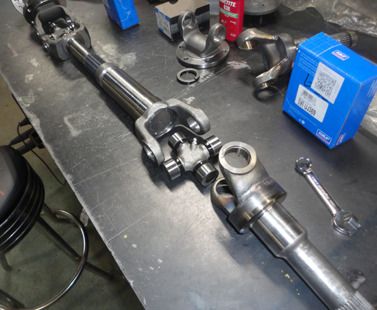
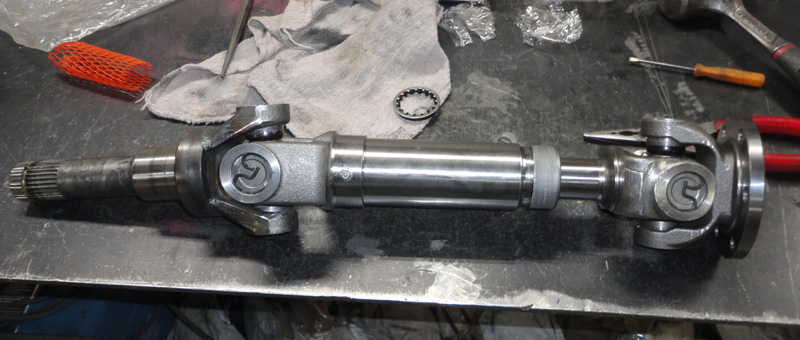
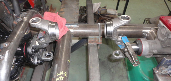
So while I was in the mood for yokes, U joints and welding I made up the drive shaft too. I cut the tube to length, squared up the ends on the handy old lathe, lined up the yokes and welded that together too. This also fits just fine and all that is left is a trip to the balancing shop for everything at some point in the future.
If nothing else I think an 8.8 can be used in an original style 289 chassis with very few changes and adapters can easily be made for original style axles too.
This all took a lot longer to do than to tell and was also not really done in one continuous process as things had to be figured out then parts had to be ordered and waited for too.
But I thought it best to edit it all into one timeline as I am still playing catch up with my posts.
I hope this meets with your approval Mr. MAP

Next time….out with the bad air…

All the best,
Hudson
.