So you've just spent some of your last dimes on obtaining a Cobra or getting it road worthy. Boy, wouldn't it be nice to have one of those Qwik Lift-type ramps to properly service your classic car without breaking out the floor jack and stands every single time? I really want a Qwik Lift....I just can't afford one right now.
Well, here's your solution that ANYONE can do by themselves with simple power tools, a little imagination and less than $250.00
complete! I got the idea during my Corvette days from another guy that built similar ramps for his C4 'Vette. I saved his photos and plans for a rainy day, and I finally decided to do something with them once I realized that keeping my Superformance spotless and mechanically sound required a lot of crawling underneath. At 6'3", even changing the plugs was a back-breaking exercise.
So if you have a 10 minutes and a cup of Joe in front of you, pull up a chair and I'll walk you through the process.
The first two shots below are of the completed ramps:

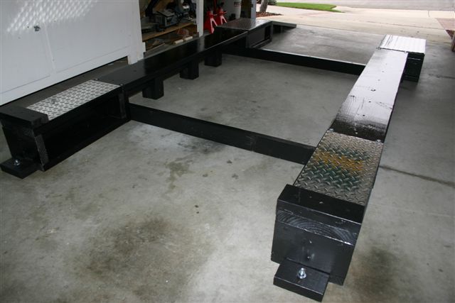
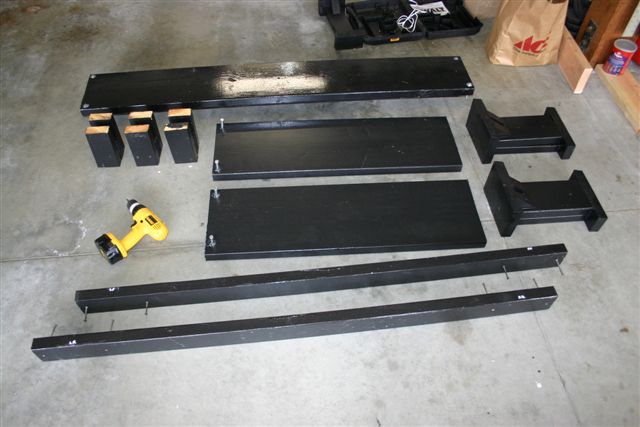
Construction materials consist of various lengths of 2x4, 2x6, 2x10 and 2x12, all coated in Kilz primer followed by flat black paint and then a two-coat topper of polyurethane (to keep the moisture out and, more importantly, to prevent splits). It's all tied together with 3" rough drywall screws, with the "through boards" pre-drilled to prevent splits when you "DeWalt them" to the receiving boards. Here are the basic pieces of the assembly:
The front pedestals are built out of 2x6 (that form an "I" in the middle), with 2x10 on top and bottom. This yields a net lift height of 8.5" (from bottom of tire with a
compressed suspension, as a 2x6 is actually 1.5x5.5 and the 2x10 is actually 1.5x9.5. Each front pedestal is 23" long and has a 2x4 "tire stop" for safety.
The rear pedestals are made a little different because.....THE REAR TRACK IS 4" WIDER THAN THE FRONT. So I had to get creative and used the 2x6s for the "I", but used three of them in the middle instead of just one. I also used 2x12 and turned them sideways, mounting two pieces side-by-side. This yielded the same overall length (23") as the front pedestals,
but it gave me a pedestal width of 14" for the rears. All four pedestals were then covered with a piece of 1/16" aluminum diamond plate. This keeps the hot tires resting on a hard, non-peeling surface (versus polyurethane), plus
I think they look trick! 
The "bridges" are 2x10 with a 2x4 "spine" right down the middle (you can't see it in this photo), with three trestles or center supports. The bridges attach to the pedestals with 3" long by.375" diameter bolts that I will call "pins" (since they just sit in the holes....you don't bolt it together....keep on reading why).
The cross supports are simple 2x4, cut to the proper wheel-center-to-wheel-center for your particular car (I believe these were cut to 62", as my front tires were 53.5" center-to-center, while the rears were 57.5"). Your measurements may vary, so triple check everything. I attach them with 2 drywall screws on each end, but I'm probably going to change this to something a little easier (perhaps threaded inserts with a bolt so that my air rachet can work them on/off easier - for now the DeWalt does the work).
The actual ramps are 2x12 cut to 38". The pin holes were drilled perpindicular to the ramps, meaning that the holes drilled into the rear of the rear pedestals were cut at a slight angle. The ramp supports were cut from scrap pieces of 2x10, 2x6 and 2x4. I don't have the exact measurements handy. I also coated the ramps with a non-slip agent on my last coat of polyurethane.
As you can see from the next photo, the assembly supports the car without any problems. Heck, our houses must support tons of roofing materials, so wood is extremely strong and rigid when cut right and engineered properly.
 Now the real beauty of this particular Poor Man's QL. With the pins removed, you can break down the whole ramp assembly.

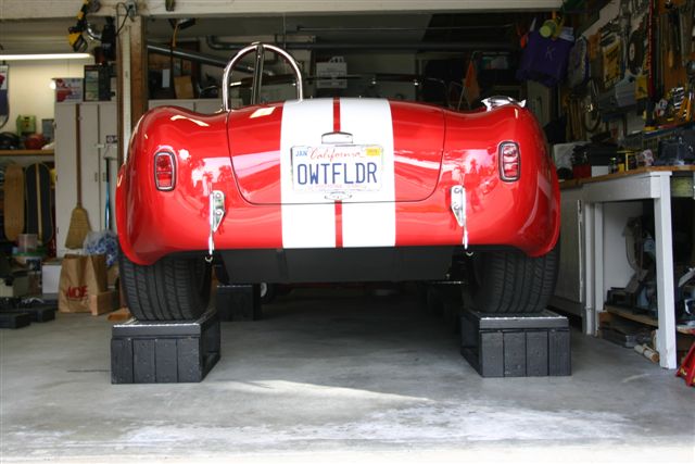
As you can clearly see, the bridges, cross-supports and rear ramps all break down with ease (under 5 minutes), and the assembly provides you with
plenty of room to work underneath for general maintenance and cleaning. You also have lots of room to jack up the car higher for more serious maintenance efforts (clutch work), or for removing the wheels for brake and suspension R&R.
A couple precautions. You can see them in the first two pictures...make sure you sink a couple concrete lugs (with wood) in front of each forward pedestal. This will keep the whole assembly from walking forward on you. Also, make all your cuts so that the wood grain is always in compression (parallel to the floor). You can't do this with the top surface areas, but the "spines" in the middle take up the load.
To help me self-align myself when driving into the garage, I placed a tennis ball and a piece of string from the ceiling. The tennis ball helps me line up my approach and the string is a double-check about 1/2 way up to ensure that I'm still tracking straight. I had a neighbor help me on the initial two tries, but I now have the hang of it.
Someday I still hope to get a
real Qwik Lift, but for now this little baby will work just fine. I can answer pretty much any question if you have one.
Regards,
-Dean