Absolute Pace

Go Back   Club Cobra > Club Forums > Australian Cobra Club

Welcome to Club Cobra!  The World's largest non biased Shelby Cobra related site!

  •  » Representation from nearly all Cobra/Daytona/GT40 manufacturers
  •  » Help from all over the world for your questions
  •  » Build logs for you and all members
  •  » Blogs
  •  » Image Gallery
  •  » Many thousands of members and nearly 1 million posts! 

YES! I want to register an account for free right now!  p.s.: For registered members this ad will NOT show

Keith Craft Racing
Nevada Classics
Keith Craft Racing
Main Menu
Nevada Classics
Nevada Classics
Keith Craft Racing
MMG Superformance
Advertise at CC
Banner Ad Rates
Keith Craft Racing
Keith Craft Racing
MMG Superformance
MMG Superformance
March 2024
S M T W T F S
          1 2
3 4 5 6 7 8 9
10 11 12 13 14 15 16
17 18 19 20 21 22 23
24 25 26 27 28 29 30
31            
  #1 (permalink)  
Old 01-07-2007, 01:40 AM
Aussie Mike's Avatar
CC Member
Visit my Photo Gallery

 
Join Date: Jan 2001
Location: Sunbury, VIC
Cobra Make, Engine: Rat Rod Racer, LS1 & T56
Posts: 5,391
Not Ranked     
Default Wilwood MC Float Switches

For those of you building CR kits with dual Wilwood or Tilton brake Master Cylinders wiring in a brake fail light is a pain.

Ian reccomends fitting float switches to the master cylinders to detect the fluid level drop when a brake circuit fails.

I just completed my float switch setup and thought I'd doccument it so that it may save someone else the stress of how to nut out adapting the float switches.

I started at my local Pick-A-Part wrecker and went down the lines of cars looking for ones with brake master cylinder float switches. There were several to choose from but the most easily adaptable looking were in mid 80's Holden Barina or Suzuki Swift. These have a remote brake reservoir with a switch built into the cap. There were a few at this yard so I pulled the switches from 2 cars and took them home for $10 each.

Here's what the Barina switch/cap looks like:
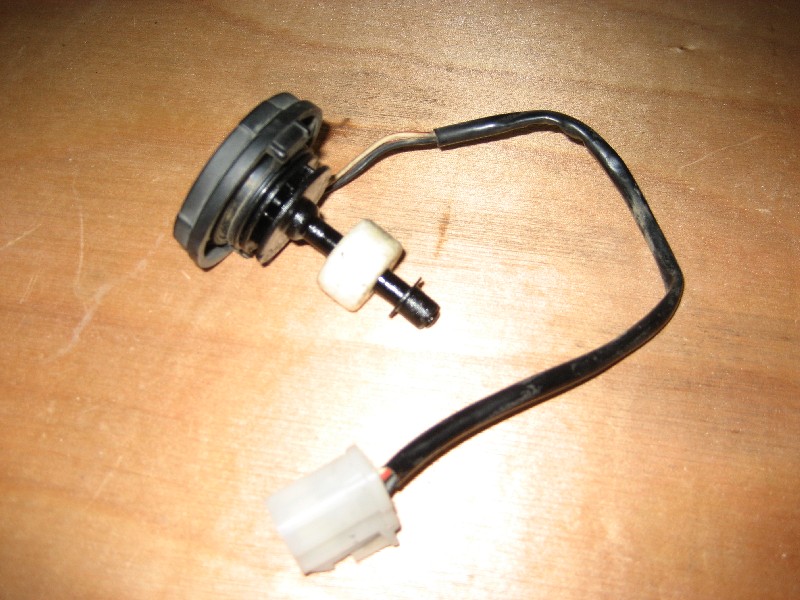


It looks like it's made by NABCO
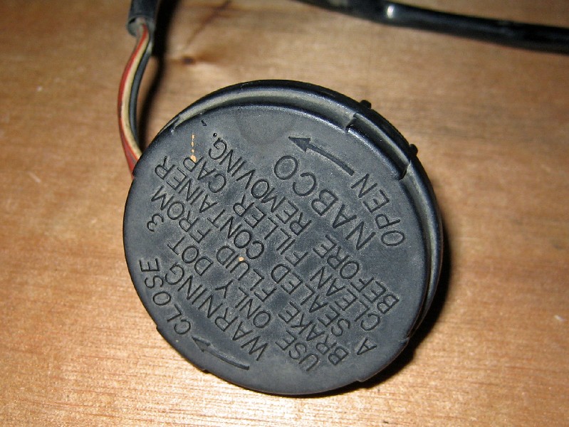


The first step is to remove the switch assembly from the cap. It clips in place and can be levered out with a screw driver. You can clip the side of the cap with some side cutters to loosen it and make it easier to get out.
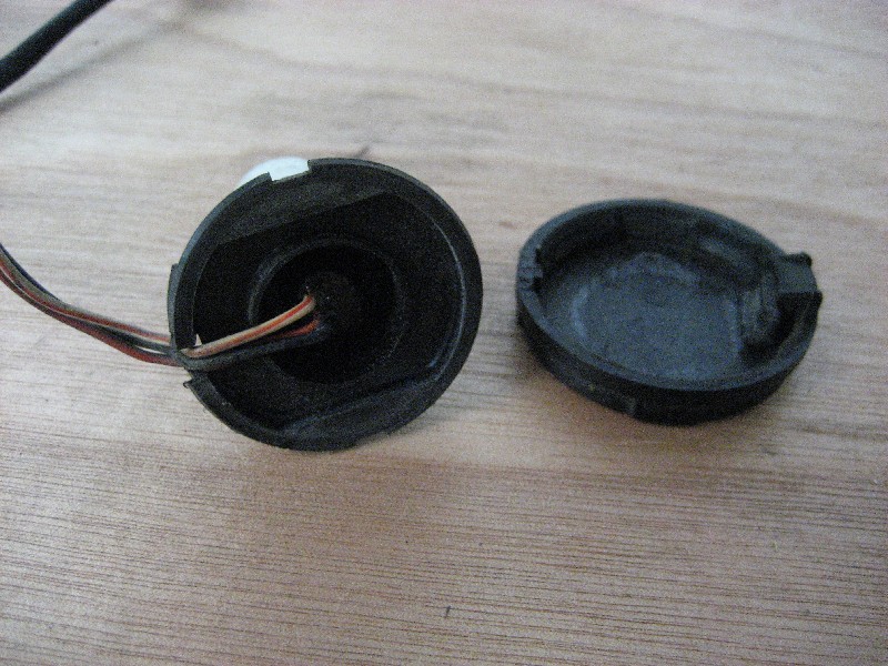


There are three wires to the switch. We only need two of them, the Black and the Red/Black. Clip off the White/Red wire.

The float switch has a reed switch inside it. The contact of this switch is normaly open. The float is a torus shaped magnet coated in foam to make it float. As the float drops down the spindle the magnet passes over the reed swich inside closing it's contacts. The black and red wires are the two switch contacts.
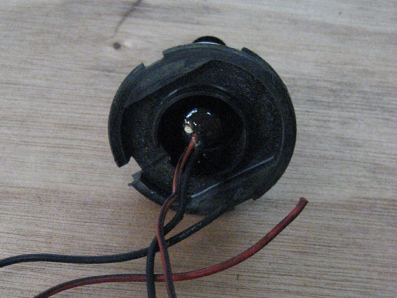


The switch needs a bit of modification before it'll fit inside the cap of the Wilwood master cylinder. Remove the rubber seal first. Just hook under it with a thin screwdriver and lever it off.
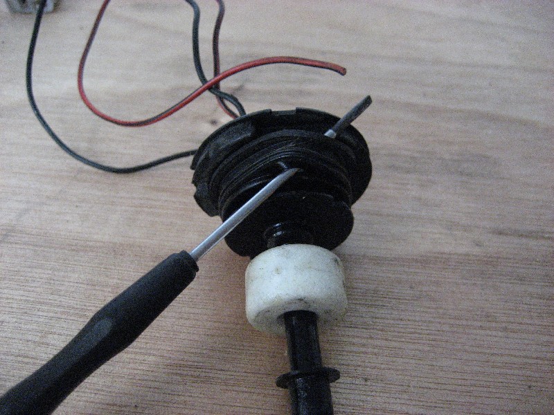


Next clip away the flange around the top of the switch being careful not to damage the center part.
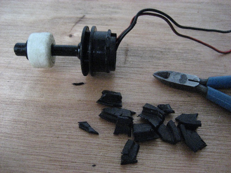


Using a file or preferably a linisher clean up the part where you removed the flange. You will also need to remove some material from the two ribs below it so it will fit in the neck of the Wilwood reservoir. Work slowly and linish it down to the strengthening ribs.

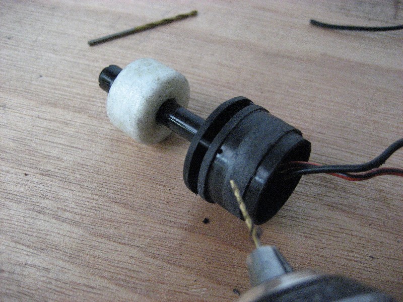
At his point you should also drill a small vent hole in the side just above the top rib. I used a 1 mm drill bit and just drilled through the outside wall. The vent is needed to equalise pressure as the fluid level drops or rises.


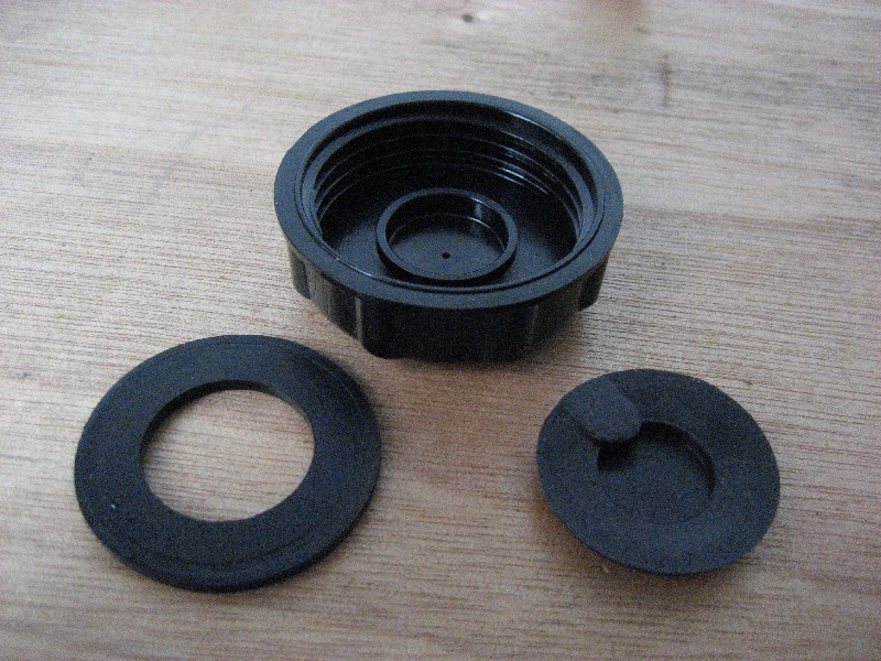
Take the wilwood cap and look at the underside. There is a plastic disk that's clipped into the center that acts as a baffle for the vent hole. This stops fluid splashing out of the vent hole.
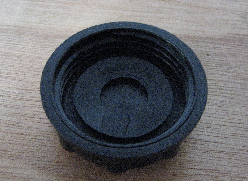


flip the baffle out with a screw driver and then carefully pull out the rubber seal under it. Hang onto the seal as we'll re use it later.


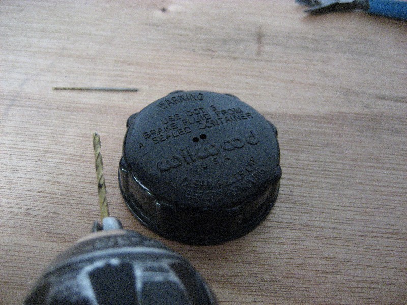
Now we need to drill some holes in the cap for the wires to come through. I used a 2 mm bit and drilled out th vent hole and put another hole next to it. We'll be adding a new vent hole later.


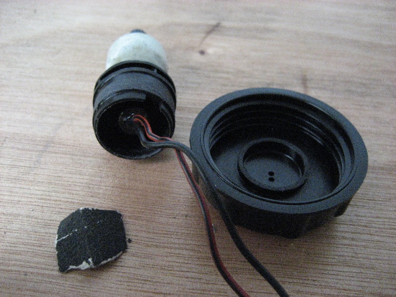
Surprisingly the inside diameter of the top of the float switch is a snap fit over the lip inside the cap where the baffle clips in. It's a fairly tight fit so you could probably get away with just clipping it all together. I thought I'd make it a bit more secure as I don't know how it'll cope with vibration over time and the cap being unscrewed to top up.

When using epoxy glue it's a good idea to roughen up both surfaces with some coarse sand paper. This will give the epoxy something to key into.
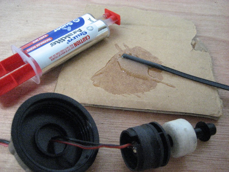


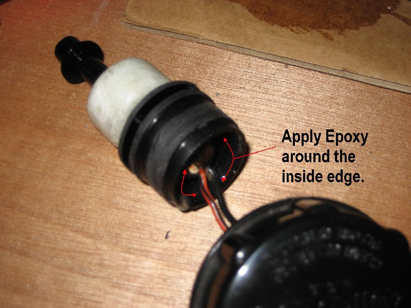
Run some glue around the inside of the top of the float switch.


A pool of epoxy around the wires where they exit the cap will secure them.
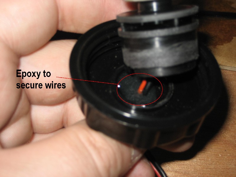


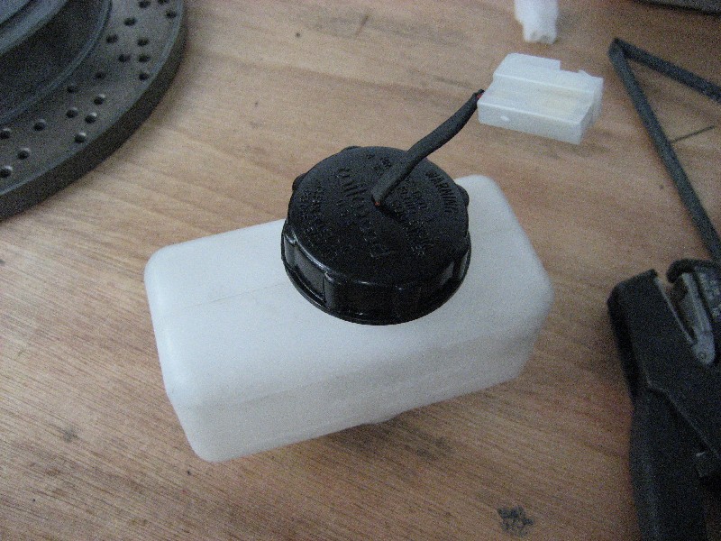
Pull the wires through and snap the float switch into place. Wipe off any excess glue from the inside of the cap and where the wires exit the cap. The 2mm in the cap holes are a snug fit around the wires so the glue shouldn't leak.

sit them upside down somewhere whilst the epoxy cures. I left mine over night.
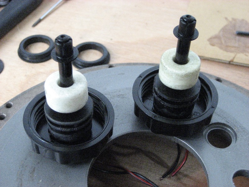


When the epoxy has cured you can run some heat shrink tubing over the wires and terminate them with your choice of connector. You can also pop the seal back into the cap. It will stretch over the float switch and settle back ito it's original position with some careful help from a screw driver.
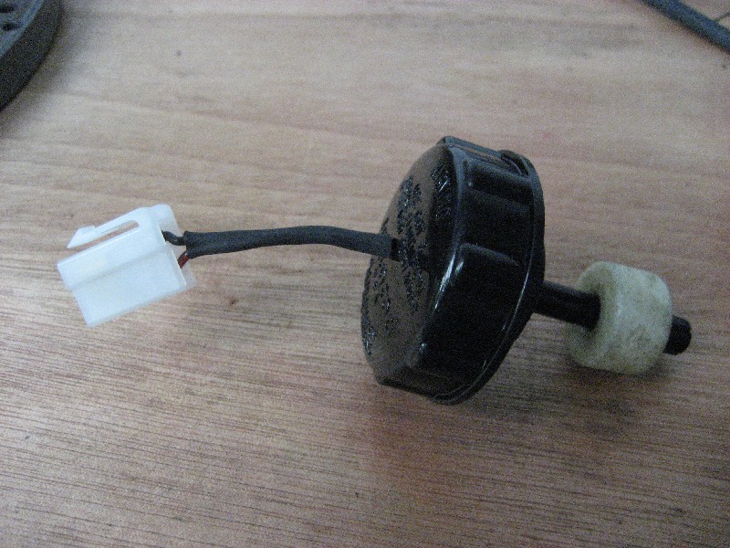


You will also need to drill a new vent hole in the cap near where the wires came through ito the space in the top of the float switch. The hole we drilled earliar in the side of the switch also goes into this cavity so we have a vent and baffle.
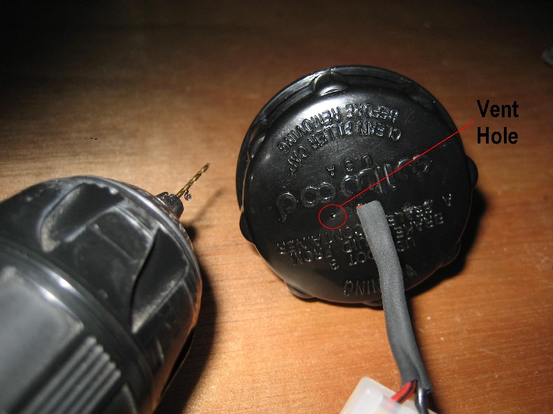


The Wilwood reservoir may have a filter element in the neck. This will have to be pulled out for the float switch equipped cap to be installed.


The float switch can now be wired up to the idiot light on your dash. If you are running two switches connect them in parrallel.
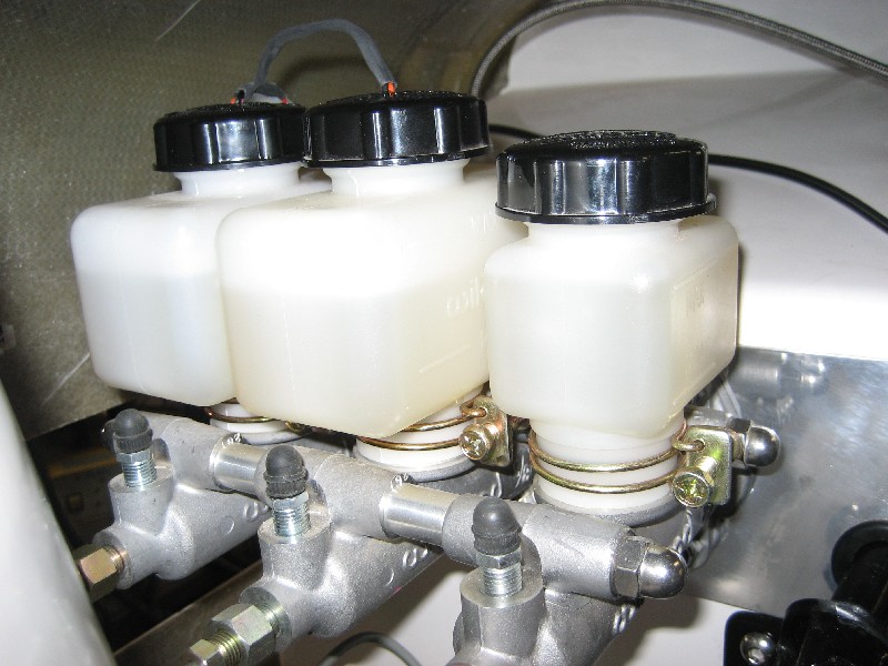


Hope this helps

Cheers
__________________
Mike Murphy
Melbourne Australia


Last edited by Aussie Mike; 01-07-2007 at 03:42 AM..
Reply With Quote
  #2 (permalink)  
Old 01-07-2007, 02:28 AM
Philm's Avatar
CC Member
Visit my Photo Gallery

 
Join Date: Feb 2006
Location: Paradise Point, Qld
Cobra Make, Engine: Absolute Pace
Posts: 1,205
Not Ranked     
Default Wow

Mike,
Incredible!!!!


Well done.

Phil
Reply With Quote
  #3 (permalink)  
Old 01-07-2007, 02:24 PM
Tenrocca's Avatar
CC Member
Visit my Photo Gallery

 
Join Date: Nov 2004
Location: Sydney, NSW
Cobra Make, Engine: Classic Revival #3199. 366ci L76, T56 6 speed, Blue circle custom paint, Australias most original cobra 2009-2010
Posts: 2,396
Not Ranked     
Default

Great work Mike - I pinched one of those float switched off an old barina a while back - and tinked a little with inserting into the willwood cap - but put it all in the too hard basket. Might have another crack at it now....looks like a bought one

Cheers.
__________________
Proudly registered since 2013.
Reply With Quote
  #4 (permalink)  
Old 01-07-2007, 02:44 PM
cobbindale's Avatar
CC Member
Visit my Photo Gallery

 
Join Date: Aug 2004
Location: Geelong, Vic
Cobra Make, Engine: Classic Revival.
Posts: 215
Not Ranked     
Default

If you struggle to find Suzuki/Barina switches, you could also try Subaru Leone of about the same vintage. Look to be the same switches and you can add another make of car to the component list that makes up your Cobra.
Great job Mike.

Cheers.
Reply With Quote
  #5 (permalink)  
Old 01-08-2007, 02:13 PM
CC Member
Visit my Photo Gallery

 
Join Date: Oct 2006
Location: Sydney, nsw
Cobra Make, Engine: CR 3205
Posts: 161
Not Ranked     
Default

Mike you truely are a master !!!!!!
Reply With Quote
  #6 (permalink)  
Old 01-08-2007, 02:37 PM
CC Member
Visit my Photo Gallery

 
Join Date: Feb 2006
Location: Melbourne, Vic
Cobra Make, Engine: Classic Revival (CR3204) 6ltr s/c, T56 6spd
Posts: 95
Not Ranked     
Default

Very Impressive Mike, Well done.
Did you/will you also wire up the hand brake switch in parrallel with these float switches??

Luke.....
Reply With Quote
  #7 (permalink)  
Old 01-08-2007, 02:43 PM
Aussie Mike's Avatar
CC Member
Visit my Photo Gallery

 
Join Date: Jan 2001
Location: Sunbury, VIC
Cobra Make, Engine: Rat Rod Racer, LS1 & T56
Posts: 5,391
Not Ranked     
Default

Thanks Guys,

The hand brake switch has a seperate idiot light on the dash. It was pretty straight forward to wire up as there's provision for mounting a push button switch on the MG hand brake lever. The wire is just gaffer taped to the side of the tunnel and will be hidden under the carpet. I'll snap a pic of it it if you like.

Good tip on the Subaru switches. It figures there must be a few cars out there that share these components.

Cheers
__________________
Mike Murphy
Melbourne Australia

Reply With Quote
  #8 (permalink)  
Old 01-08-2007, 09:03 PM
Gav's Avatar
Gav Gav is offline
CC Member
Visit my Photo Gallery

 
Join Date: Apr 2006
Location: Mildura, vic
Cobra Make, Engine: FFR Coupe, 416ci of LS goodness
Posts: 2,349
Not Ranked     
Default

Nice work Mikey
Reply With Quote
  #9 (permalink)  
Old 01-30-2007, 10:39 PM
CC Member
Visit my Photo Gallery

 
Join Date: Sep 2006
Cobra Make, Engine:
Posts: 56
Not Ranked     
Default

Mike,
This is almost exactly how we decribe it in the wiring instructions. However, you have made one slight error that I feel we should rectify so other do not follow these instructions. DO NOT CUT OFF THE WHITE/RED WIRE.
Under the ADR's the light MUST come on when the system fails & when you turn on the igition. This function is performed by the white/red wire when it is wired into the alternator light circuit.
Your current installation will not pass engineering & will need to be changed.
Cheers,
Ian
Reply With Quote
  #10 (permalink)  
Old 01-31-2007, 02:19 AM
CC Member
Visit my Photo Gallery

 
Join Date: Feb 2003
Location: Melbourne, VIC
Cobra Make, Engine: DRB,Ford Tickford 302 220kw with BTR 4 speed auto, 3.9:1 LSD
Posts: 491
Not Ranked     
Default

Fantastic post Mike,

People like you make this forum great. Your post will certainly save some people time and money and give people the confidence to try things themselves.
__________________
Cameron
Reply With Quote
  #11 (permalink)  
Old 01-31-2007, 03:08 AM
acecob's Avatar
CC Member
Visit my Photo Gallery

 
Join Date: Jan 2007
Location: Sydney, NSW
Cobra Make, Engine: DRB. Engine out :)
Posts: 517
Not Ranked     
Default

Thats a great post guys, nice detail.
I'm new in here and stay on for a while , haven't looked at porn for three days. Its great !

Keep it up
__________________
"I'd open my mind, but I don't want the stupid to corrupt it."
Reply With Quote
  #12 (permalink)  
Old 01-31-2007, 06:26 PM
Mando's Avatar
CC Member
Visit my Photo Gallery

 
Join Date: Jul 2004
Cobra Make, Engine: 347 Stroker Morrison Injection. Registered.
Posts: 1,440
Not Ranked     
Default

Hi guys, the reservoirs on my Wilwoods have bayonet fittings and not thread like Aussie Mike has. That means that the float caps from an 85 Barina or Swift will fit directly into the reservoir without modification. Im ordering some on Monday morning for Gavin Irvine so if anyone wants some let me know and Ill order more. They cost under US$10 each plus delivery.
Ph. 0407 80 70 60.

Regards.
__________________
Mando

Last edited by Mando; 02-01-2007 at 09:28 PM..
Reply With Quote
  #13 (permalink)  
Old 02-01-2007, 10:39 PM
CC Member
Visit my Photo Gallery

 
Join Date: Jan 2005
Location: Geelong, Vic, Aus, VIC
Cobra Make, Engine: The one leaving fat black marks
Posts: 240
Not Ranked     
Default

Nice work Mike, where did you get the MC from and what sort of $$ are you looking at?

Todd
Reply With Quote
  #14 (permalink)  
Old 02-02-2007, 02:18 AM
Aussie Mike's Avatar
CC Member
Visit my Photo Gallery

 
Join Date: Jan 2001
Location: Sunbury, VIC
Cobra Make, Engine: Rat Rod Racer, LS1 & T56
Posts: 5,391
Not Ranked     
Default

I've found about the best price locally for the Wilwood MC kits is $108 from VPW http://www.vpw.com.au

Some of the guys have bought them from the US and got them cheaper but if you don't want to wait for the post $108 isn't too bad.

What are you thinking about fitting them to Todd?

Cheers
__________________
Mike Murphy
Melbourne Australia

Reply With Quote
  #15 (permalink)  
Old 02-02-2007, 02:24 AM
CC Member
Visit my Photo Gallery

 
Join Date: Jan 2005
Location: Geelong, Vic, Aus, VIC
Cobra Make, Engine: The one leaving fat black marks
Posts: 240
Not Ranked     
Default

I have this to go in my '02...


I have to update the M/C to split system and have to work out what is the most cost affective way of doing it... a new BMW part or aftermarket...

Cheers,

Todd
Reply With Quote
  #16 (permalink)  
Old 02-02-2007, 02:33 AM
Aussie Mike's Avatar
CC Member
Visit my Photo Gallery

 
Join Date: Jan 2001
Location: Sunbury, VIC
Cobra Make, Engine: Rat Rod Racer, LS1 & T56
Posts: 5,391
Not Ranked     
Default

Very nice Todd. I'd probably look at getting the whole wilwood pedal box. They do a couple of 2 pedal combination units that do the clutch and have a dual MC and ballance bar setup for the brakes. Look pretty trick too and only $298 from VPW plus master cylinders.

With the booster and existing clutch MC gone there should be plenty of space to mount something. They have versions you could sandwich the MC on the outside of the fire wall and the pedal box inside.

If you are running a cable clutch then the single pedal assembly is only $166.

Food for thought.

Cheers
__________________
Mike Murphy
Melbourne Australia

Reply With Quote
  #17 (permalink)  
Old 02-02-2007, 02:48 AM
CC Member
Visit my Photo Gallery

 
Join Date: Jan 2005
Location: Geelong, Vic, Aus, VIC
Cobra Make, Engine: The one leaving fat black marks
Posts: 240
Not Ranked     
Default

Thanks Mike... I will look into it.

Cheers,

Todd
Reply With Quote
  #18 (permalink)  
Old 02-07-2007, 03:50 AM
Aussie Mike's Avatar
CC Member
Visit my Photo Gallery

 
Join Date: Jan 2001
Location: Sunbury, VIC
Cobra Make, Engine: Rat Rod Racer, LS1 & T56
Posts: 5,391
Not Ranked     
Default

Quote:
Originally Posted by Classic Revival
Mike,
This is almost exactly how we decribe it in the wiring instructions. However, you have made one slight error that I feel we should rectify so other do not follow these instructions. DO NOT CUT OFF THE WHITE/RED WIRE.
Under the ADR's the light MUST come on when the system fails & when you turn on the igition. This function is performed by the white/red wire when it is wired into the alternator light circuit.
Your current installation will not pass engineering & will need to be changed.
Cheers,
Ian
I haven't seen anything in any of the manuals I have that describes how to do this. It must be in another manual
I haven't seen.

I've been thinking about the way you suggest wiring it up and can see a bit of a problem. What happens when you get a charge fail problem and the charge light comes on? It seems to me you would get a brake fail warning as well.

I think a better way would be to use a delay circuit much like the seat belt warning light to short the float contacts for 10 seconds when the key is turned on.

Cheers
__________________
Mike Murphy
Melbourne Australia

Reply With Quote
  #19 (permalink)  
Old 02-07-2007, 05:21 AM
CC Member
Visit my Photo Gallery

 
Join Date: Feb 2006
Location: Perth, WA
Cobra Make, Engine: G-Force kit, LS1, 4L60, 4.09 LSD... Gone to Queensland!!!
Posts: 588
Not Ranked     
Default

Makes sense to me Mike.
If you have no charge then you can't drive the car, hence you won't need brakes. Alternatively, if you have no brakes it doesn't matter if you don't have charge, you can't really drive the car anyway....
__________________
www.ls1tune.com Tuning the Dark Side
Reply With Quote
  #20 (permalink)  
Old 02-11-2007, 02:21 AM
CC Member
Visit my Photo Gallery

 
Join Date: Sep 2006
Cobra Make, Engine:
Posts: 56
Not Ranked     
Default

Mike,
The reason you have not see this in any manual is because you have not purchased the wiring harness with the manual!
No, the fail light does not come on when you have a charge problem. This is the way most of these lights are wired on production vehicles.
Cheers,
Ian
Reply With Quote
Reply


Thread Tools
Display Modes Rate This Thread
Rate This Thread:

Posting Rules
You may not post new threads
You may not post replies
You may not post attachments
You may not edit your posts

BB code is On
Smilies are On
[IMG] code is On
HTML code is Off
Trackbacks are On
Pingbacks are On
Refbacks are On


All times are GMT -7. The time now is 12:10 AM.


Powered by vBulletin® Version 3.8.0
Copyright ©2000 - 2024, Jelsoft Enterprises Ltd.
Search Engine Friendly URLs by vBSEO 3.6.0
The representations expressed are the representations and opinions of the clubcobra.com forum members and do not necessarily reflect the opinions and viewpoints of the site owners, moderators, Shelby American, any other replica manufacturer, Ford Motor Company. This website has been planned and developed by clubcobra.com and its forum members and should not be construed as being endorsed by Ford Motor Company, or Shelby American or any other manufacturer unless expressly noted by that entity. "Cobra" and the Cobra logo are registered trademarks for Ford Motor Co., Inc. clubcobra.com forum members agree not to post any copyrighted material unless the copyrighted material is owned by you. Although we do not and cannot review the messages posted and are not responsible for the content of any of these messages, we reserve the right to delete any message for any reason whatsoever. You remain solely responsible for the content of your messages, and you agree to indemnify and hold us harmless with respect to any claim based upon transmission of your message(s). Thank you for visiting clubcobra.com. For full policy documentation refer to the following link: CC Policy