Club Cobra Keith Craft Motorsports  

Go Back   Club Cobra > Manufacturers, Engine Builders, tools, and parts. > ERA---Speak with Bob Putnam

MMG Superformance
Nevada Classics
MMG Superformance
Main Menu
Module Jump:
Nevada Classics
Nevada Classics
MMG Superformance
Keith Craft Racing
Advertise at CC
Banner Ad Rates
MMG Superformance
MMG Superformance
MMG Superformance
November 2025
S M T W T F S
            1
2 3 4 5 6 7 8
9 10 11 12 13 14 15
16 17 18 19 20 21 22
23 24 25 26 27 28 29
30            

Kirkham Motorsports

Like Tree12Likes

Reply
 
LinkBack Thread Tools Display Modes
  #1 (permalink)  
Old 02-12-2016, 05:42 PM
CC Member
Visit my Photo Gallery

 
Join Date: Sep 2012
Location: Portland, OR
Cobra Make, Engine: ERA - B2Motorsports Dart 331
Posts: 464
Not Ranked     
Default

I wish I would have said -

1) in plan, the rear upright has to be able to rotate about it's vertical axis in both clockwise (anti-squat) and counter clockwise (toe) directions. Can't do it with hard bushings.

2) hard mounting the cradle requires that the assembly tolerances are quite good from ERA. Mine are - YMMV I can see how this could go bad - cradle not square to chassis.

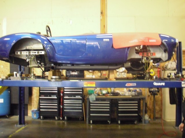
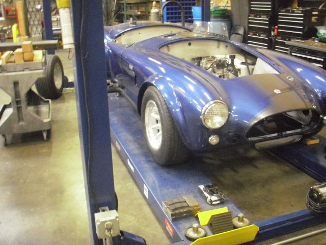
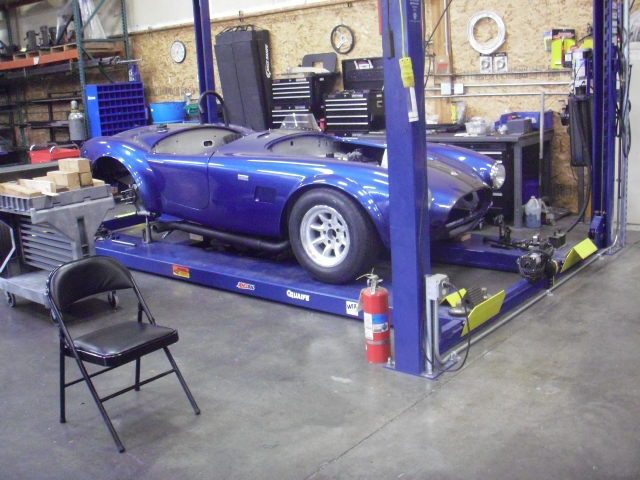
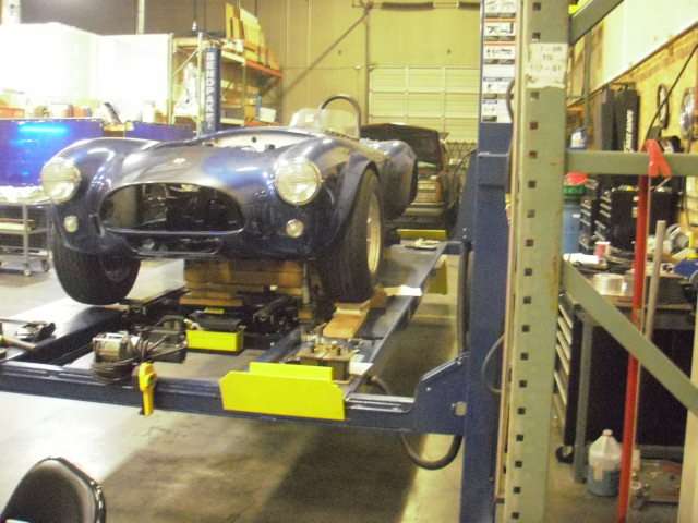
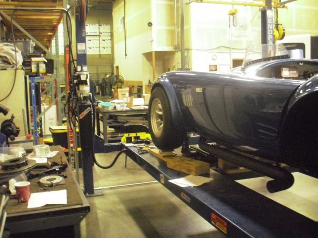
We started final fit of the cradle and rear suspension. Next week we will square it to the front and try to understand the 16.5 trailing arm length and will know just how square the cradle is to the chassis.

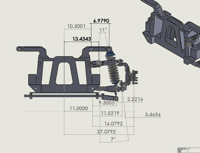
Trying to understand the 16.5 dim with respect to the wheelbase. I will call ERA but would like to understand as much as I can before I call them.


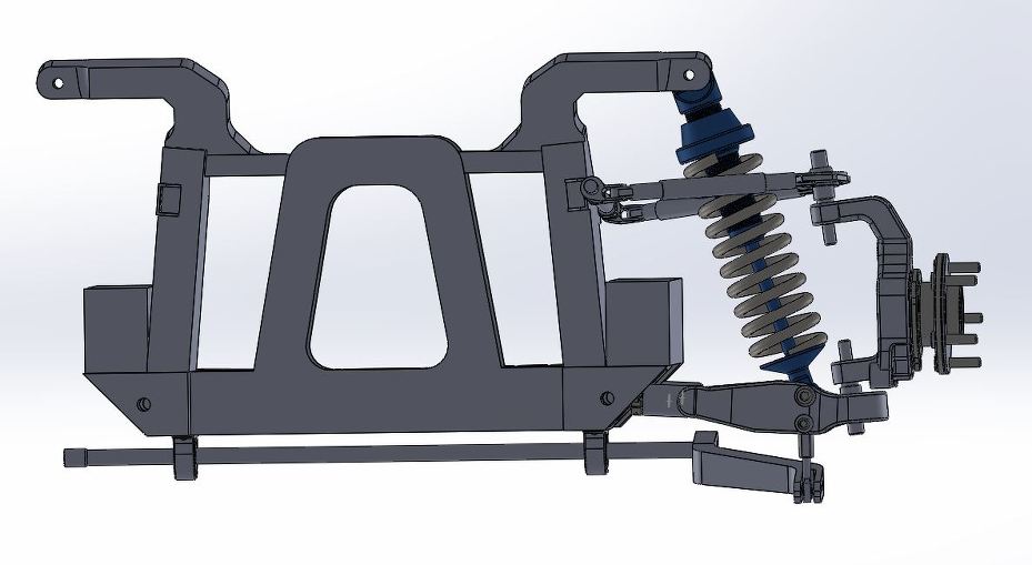
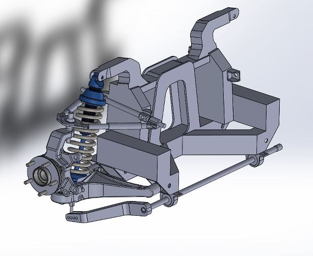
Trailing link @ 15.5 Wheelbase @ 90. Top link in double shear.


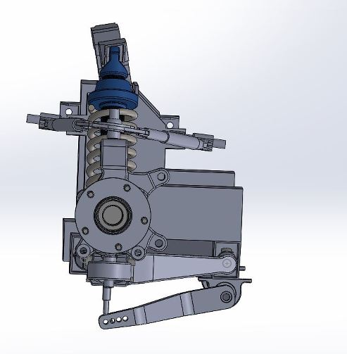
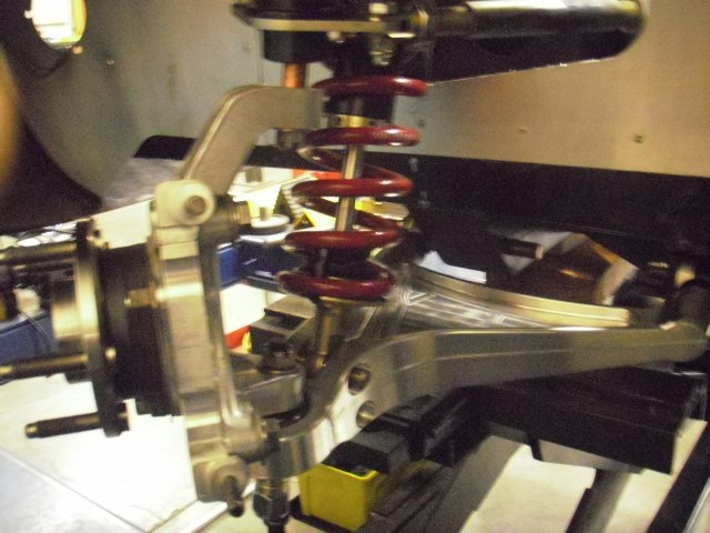
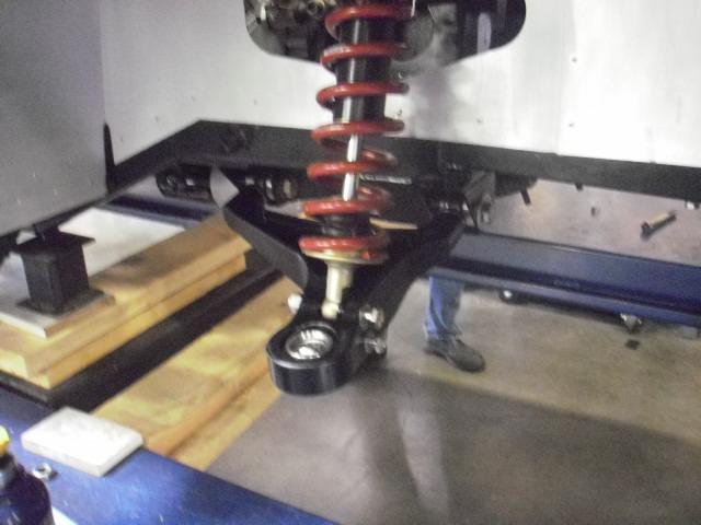
Urethane bushings reinstalled at upright - Delrin @ top of cradle


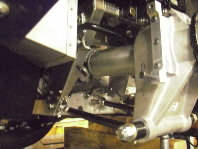
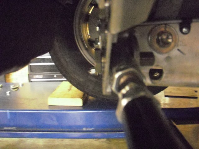
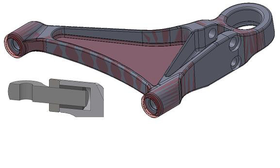
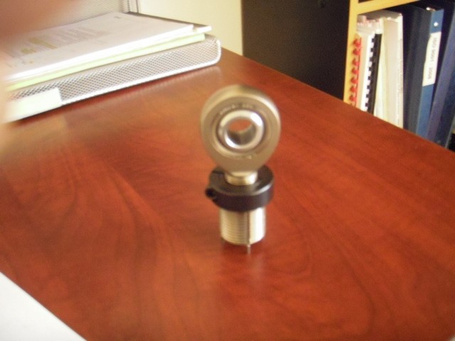
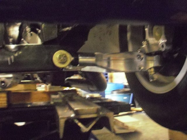
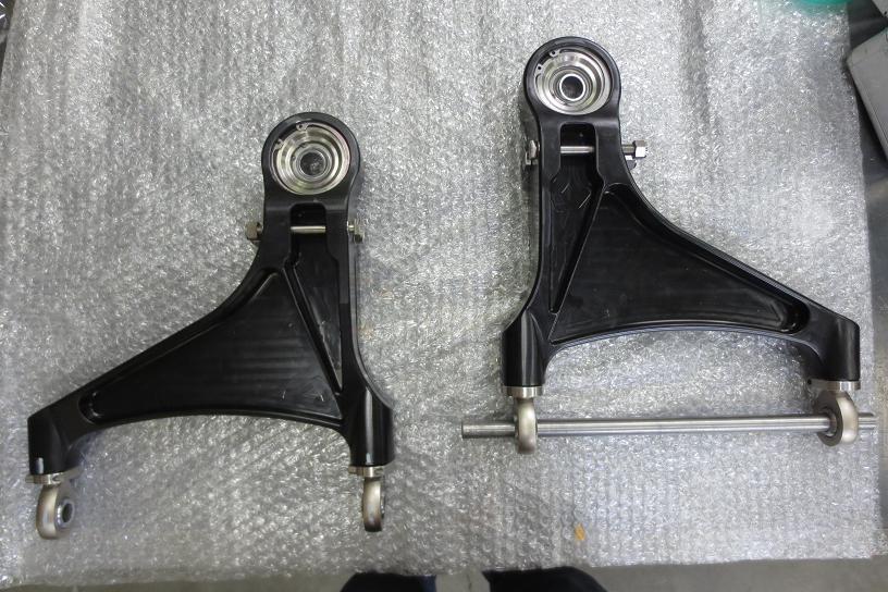
This is the pivot we are concerned with. There is .100 total gap left after rod end is inserted. If trailing link is too long this link is pushed back against the cradle. Any reward motion and the un-tapered portion of the rod end hits the cradle. We are building spacers to center the rod end in the mount.This will allow the link to rotate thru the bearing and hopefully not kiss the cradle. We are going to relieve a little material at the cradle to assure the un-tapered portion of the rod end does not touch.


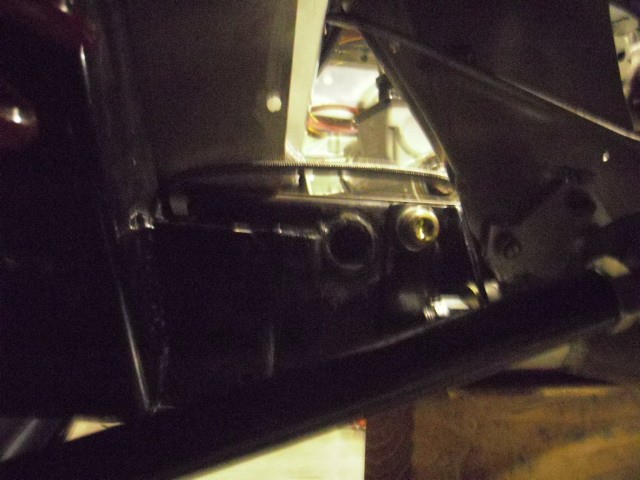
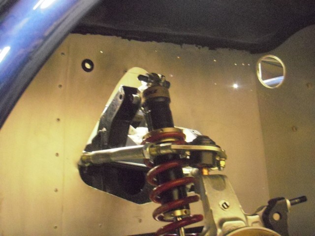
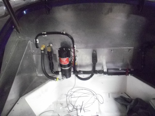
Fuel line passage - Delrin at cradle front. With the top secure the front mounts rested against the cross member with no load. Bolts were threaded by hand. Very impressive ERA.


We bump stopped the front and increased track .250 per side. Since we are fabbing new arms I took it. With the front control arms horizontal, ground clearance at front of chassis = 4.250
Bump = 1.625
Droop = 1.875.

So with the front geometry square we've dropped the CG .500.


Start milling link spacers next week.
Reply With Quote
  #2 (permalink)  
Old 02-12-2016, 06:16 PM
CC Member
Visit my Photo Gallery

 
Join Date: Sep 2012
Location: Portland, OR
Cobra Make, Engine: ERA - B2Motorsports Dart 331
Posts: 464
Not Ranked     
Default

I also wanted to show you guy's our stabar concept for the front. We are running the last iteration of FEA on the front arm so hopefully we will machine them next week.

We measured around 2.500 from the bottom of the frame rail to the bottom of the front rear pivot. Since I am going to sheet the bottom of the car and I plan to run it all the way to the back of the front spoiler we have that room to mount the sta-bar in that volume. This will help me with raising the rack and loads all of bar into the the front cross member.


Reply With Quote
  #3 (permalink)  
Old 02-15-2016, 08:16 PM
CC Member
Visit my Photo Gallery

 
Join Date: Sep 2012
Location: Portland, OR
Cobra Make, Engine: ERA - B2Motorsports Dart 331
Posts: 464
Not Ranked     
Default


We got the last iteration of the lower control arm back today. The rod ends are nearly SF 3. Our original goal was SF2. We will machine them in the next couple of days.


I read in Allen Staniforths book about Jaguar not using jam nuts, rather they used a clamping system to reduce stress in the threads. We added Keen certs and collars to the rod ends ends.


This represents all five iterations of the FEA

Reply With Quote
  #4 (permalink)  
Old 02-25-2016, 06:47 PM
CC Member
Visit my Photo Gallery

 
Join Date: Sep 2012
Location: Portland, OR
Cobra Make, Engine: ERA - B2Motorsports Dart 331
Posts: 464
Not Ranked     
Default

Our new arm - 11/16 longer (11.312) Motion Ratio = .88

What ever friction there is, is not discernible. It is very smooth. Attached to the chassis the arm under it's own weight repeats on a scale over and over @ 3.06.


Front track => 55.375 - Tread is inside the flare. Section width is a touch outside.


You can get an idea of how far out we are rotating the top of the shocks. We are working on a new UCA bearing housing trying to get an 80 degree shock angle. We have 77 with this setup. Minimum clearance is at full droop.

Reply With Quote
  #5 (permalink)  
Old 02-26-2016, 08:19 PM
CC Member
Visit my Photo Gallery

 
Join Date: Sep 2012
Location: Portland, OR
Cobra Make, Engine: ERA - B2Motorsports Dart 331
Posts: 464
Not Ranked     
Default

I had forgotten the 3 different back spacing's I have used to get here and mindlessly used the difference of the two arm lengths to guess track. That is incorrect. The drawing below shows how far out we have moved things. Our track is very close to 54 (8" rim 4" BS). The rotor hats are .280 thick so that puts us at 54.715. We cannot run anymore backspace as the calipers are within .020 of the spokes.

Scrub is still reasonable with the more vertical SAI because we were able to move the lower ball joint closer to the center of the wheel.

I sprung the car @ 2hz on paper some time back, because of the improved motion ratio and reduced shock angle, we are able to get 2hz with a 325 lb spring instead of 450.


I have been using a suspension analyzer on this suspension for the last couple of years and after a lot of hours I learned that if I move the upper pickup points 3.015 outboard, the front roll center does not migrate vertically or horizontally at 2 degrees of roll. I read somewhere that the UCA being 60% of the lower will typically achieve good timing between the two arcs. Moving the pivot outboard makes the new arm 63% the length of the lower. Seemed like a good sanity check. With this timing and static camber @ -1.5 the outer wheel is vertical at 2 deg roll.

This is the new upper pivot axle beam we are going to try. Also working on a new bearing housing out at the end. This will allow us to tip the shock out a little more. Thinking of running stress analysis on the cantilevered shock mount, the pivot axle, and the CA bearing housing.


Some pictures of the tire with respect to the flare.


No spacer, no extended ball joint, lower arm parallel to ground.


Reply With Quote
  #6 (permalink)  
Old 05-18-2016, 08:24 PM
CC Member
Visit my Photo Gallery

 
Join Date: Sep 2012
Location: Portland, OR
Cobra Make, Engine: ERA - B2Motorsports Dart 331
Posts: 464
Not Ranked     
Default

Time finally became available on the CNC. We had them hard anodized.


We bolted it all together and setup the front end with -1.5 camber and the tires are inside the flares - we gained 1.375 front track. I am happy about this since we are running a 225 front tire and I have been concerned some about tripping over the front. You can see we put the front leg in double shear. I had the stock arms measured on a CMM some time ago. Interestingly the new arms ended up 1" longer to one thousands of an inch. I was surprised by this because we did not approach from this view. Instead, maintaining the tires inside, we as-built to the best fit of the components.


We could not use our modified neck for the fuel cap. There was just no way to get the vent line connected. There is not enough clearance between the inner glass and the top of the tank. We pulled the tank and had a full length return line welded in on the driver side. We machined a new straight thru neck for the cap.


I am really happy to have the front arms done. We used the front cross member for datum and shimmed the displacement from the cross member to the center of the rod ends to the same spec as stock.

We set and reset the rear diff assembly more than several times. It is amazingly square to the chassis, but unfortunately rotated down 2 degrees with respect to engine level. We did not check the machining of the dif housing, but I have a feeling this is where it is. We made new "cradle to cross member" brackets which allowed us to rotate the cradle up 2 degrees. I realize this will reduce the anti-squat and I have not studied yet if there are other mechanical problems. If anyone can advise, please do.

I have given some thought to machining a new lower cradle tray with no anti-squat and adjustable pickup points. This would dictate that the rear upright rotates normal in the transverse plane and would allow optimization of the rear RC when changing ride heights.

I took some rough measurements and ran the rear thru a suspension analyzer and was very surprised how good the rear roll center looks. I still can't get the dimensions in the book to work on a 90" wheel base without binding the rear rod ends against the rear of the cradle. Now that the front is located we can really square and finalize the rear. The trailing rods will be what they will.

Lastly we bled the clutch - unbelievable
Reply With Quote
Reply


Posting Rules
You may not post new threads
You may not post replies
You may not post attachments
You may not edit your posts

BB code is On
Smilies are On
[IMG] code is On
HTML code is Off
Trackbacks are On
Pingbacks are On
Refbacks are On


All times are GMT -7. The time now is 10:03 AM.


Powered by vBulletin® Version 3.8.0
Copyright ©2000 - 2025, Jelsoft Enterprises Ltd.
Search Engine Friendly URLs by vBSEO 3.6.0
The representations expressed are the representations and opinions of the clubcobra.com forum members and do not necessarily reflect the opinions and viewpoints of the site owners, moderators, Shelby American, any other replica manufacturer, Ford Motor Company. This website has been planned and developed by clubcobra.com and its forum members and should not be construed as being endorsed by Ford Motor Company, or Shelby American or any other manufacturer unless expressly noted by that entity. "Cobra" and the Cobra logo are registered trademarks for Ford Motor Co., Inc. clubcobra.com forum members agree not to post any copyrighted material unless the copyrighted material is owned by you. Although we do not and cannot review the messages posted and are not responsible for the content of any of these messages, we reserve the right to delete any message for any reason whatsoever. You remain solely responsible for the content of your messages, and you agree to indemnify and hold us harmless with respect to any claim based upon transmission of your message(s). Thank you for visiting clubcobra.com. For full policy documentation refer to the following link: CC Policy
Links monetized by VigLink