For those of you building CR kits with dual Wilwood or Tilton brake Master Cylinders wiring in a brake fail light is a pain.
Ian reccomends fitting float switches to the master cylinders to detect the fluid level drop when a brake circuit fails.
I just completed my float switch setup and thought I'd doccument it so that it may save someone else the stress of how to nut out adapting the float switches.
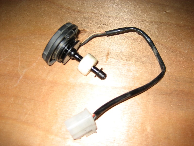
I started at my local Pick-A-Part wrecker and went down the lines of cars looking for ones with brake master cylinder float switches. There were several to choose from but the most easily adaptable looking were in mid 80's Holden Barina or Suzuki Swift. These have a remote brake reservoir with a switch built into the cap. There were a few at this yard so I pulled the switches from 2 cars and took them home for $10 each.
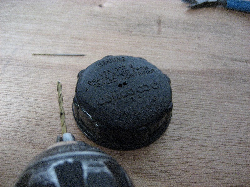
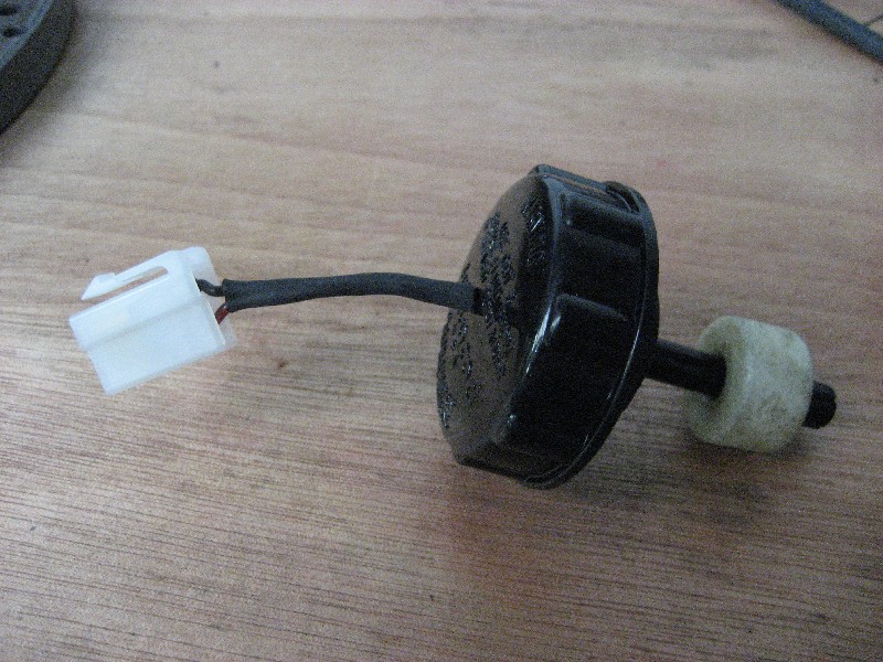
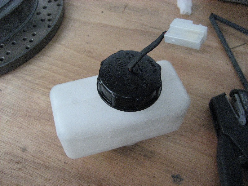
Here's what the Barina switch/cap looks like:
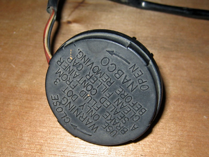
It looks like it's made by NABCO
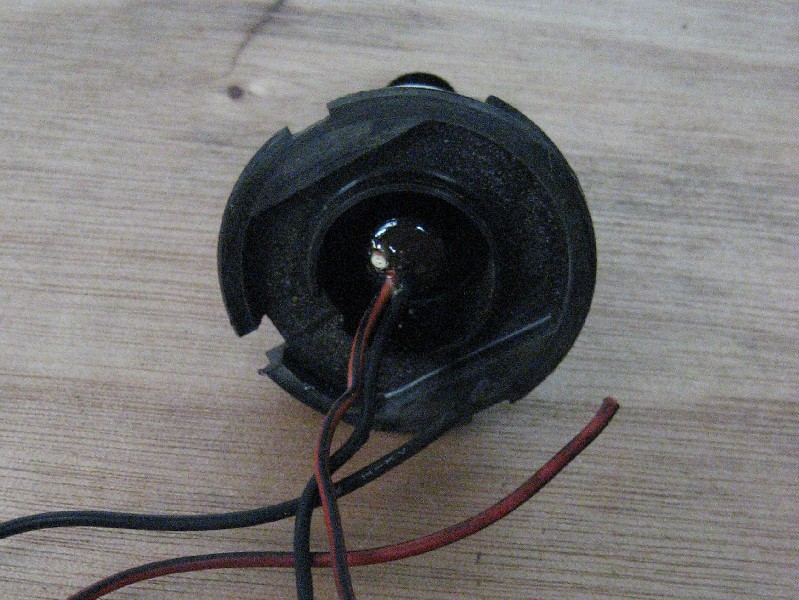
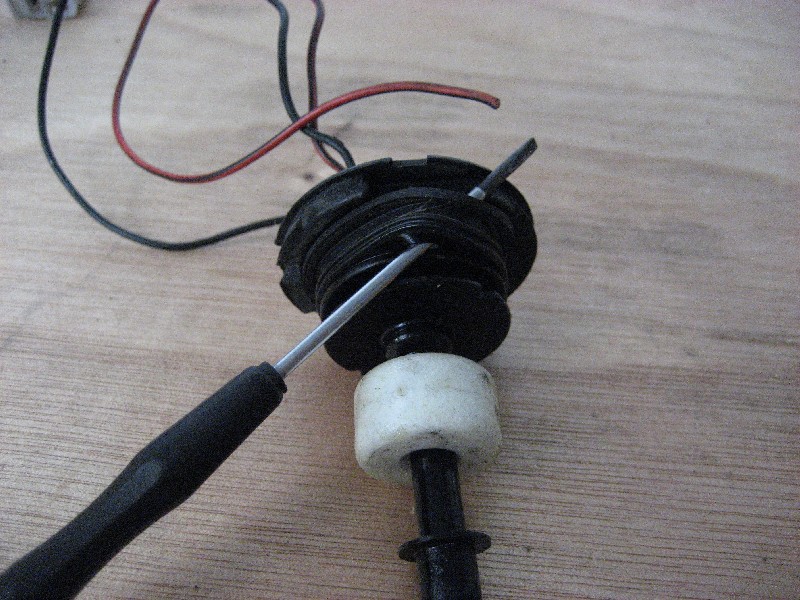
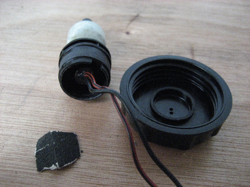
The first step is to remove the switch assembly from the cap. It clips in place and can be levered out with a screw driver. You can clip the side of the cap with some side cutters to loosen it and make it easier to get out.
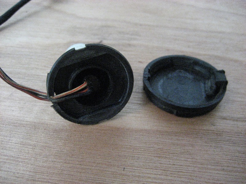
There are three wires to the switch. We only need two of them, the Black and the Red/Black. Clip off the White/Red wire.
The float switch has a reed switch inside it. The contact of this switch is normaly open. The float is a torus shaped magnet coated in foam to make it float. As the float drops down the spindle the magnet passes over the reed swich inside closing it's contacts. The black and red wires are the two switch contacts.
The switch needs a bit of modification before it'll fit inside the cap of the Wilwood master cylinder. Remove the rubber seal first. Just hook under it with a thin screwdriver and lever it off.
Next clip away the flange around the top of the switch being careful not to damage the center part.
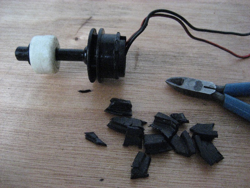
Using a file or preferably a linisher clean up the part where you removed the flange. You will also need to remove some material from the two ribs below it so it will fit in the neck of the Wilwood reservoir. Work slowly and linish it down to the strengthening ribs.
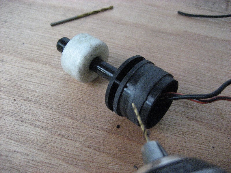
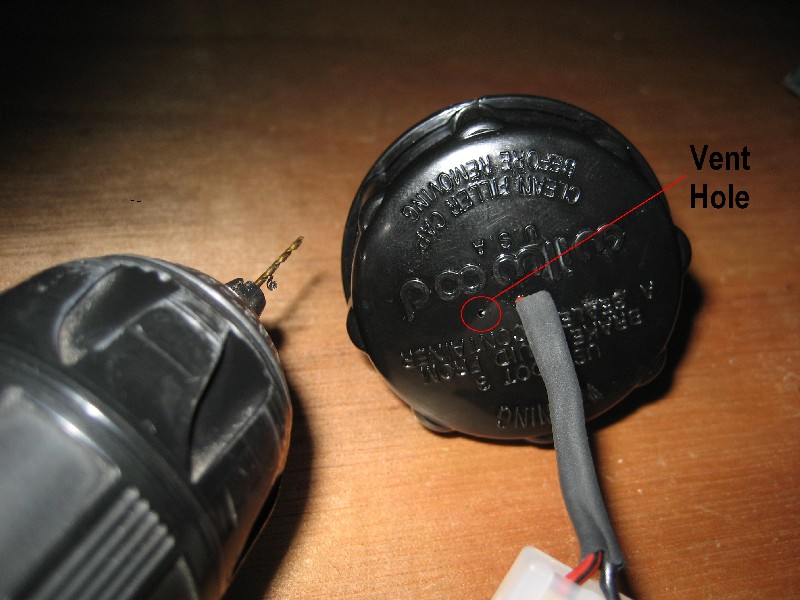
At his point you should also drill a small vent hole in the side just above the top rib. I used a 1 mm drill bit and just drilled through the outside wall. The vent is needed to equalise pressure as the fluid level drops or rises.
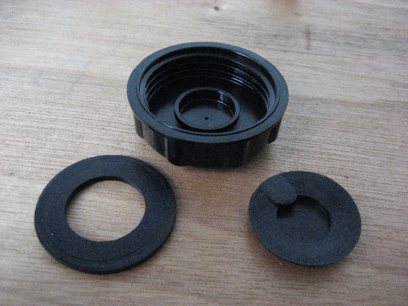
Take the wilwood cap and look at the underside. There is a plastic disk that's clipped into the center that acts as a baffle for the vent hole. This stops fluid splashing out of the vent hole.
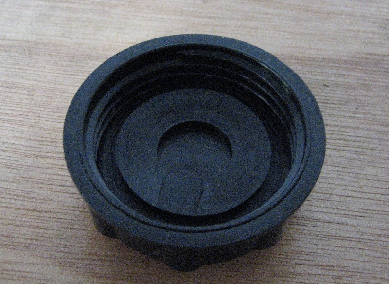
flip the baffle out with a screw driver and then carefully pull out the rubber seal under it. Hang onto the seal as we'll re use it later.
Now we need to drill some holes in the cap for the wires to come through. I used a 2 mm bit and drilled out th vent hole and put another hole next to it. We'll be adding a new vent hole later.
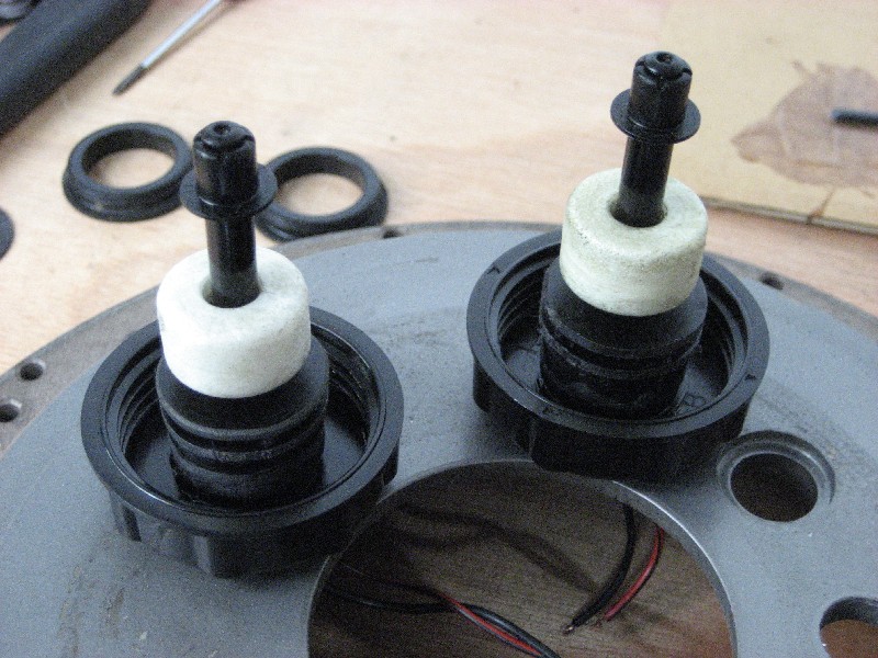
Surprisingly the inside diameter of the top of the float switch is a snap fit over the lip inside the cap where the baffle clips in. It's a fairly tight fit so you could probably get away with just clipping it all together. I thought I'd make it a bit more secure as I don't know how it'll cope with vibration over time and the cap being unscrewed to top up.
When using epoxy glue it's a good idea to roughen up both surfaces with some coarse sand paper. This will give the epoxy something to key into.
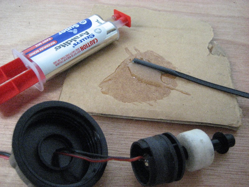
Run some glue around the inside of the top of the float switch.
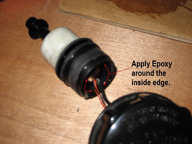
A pool of epoxy around the wires where they exit the cap will secure them.
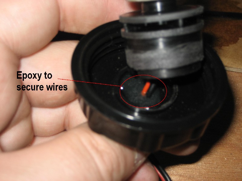
Pull the wires through and snap the float switch into place. Wipe off any excess glue from the inside of the cap and where the wires exit the cap. The 2mm in the cap holes are a snug fit around the wires so the glue shouldn't leak.
sit them upside down somewhere whilst the epoxy cures. I left mine over night.
When the epoxy has cured you can run some heat shrink tubing over the wires and terminate them with your choice of connector. You can also pop the seal back into the cap. It will stretch over the float switch and settle back ito it's original position with some careful help from a screw driver.
You will also need to drill a new vent hole in the cap near where the wires came through ito the space in the top of the float switch. The hole we drilled earliar in the side of the switch also goes into this cavity so we have a vent and baffle.
The Wilwood reservoir may have a filter element in the neck. This will have to be pulled out for the float switch equipped cap to be installed.
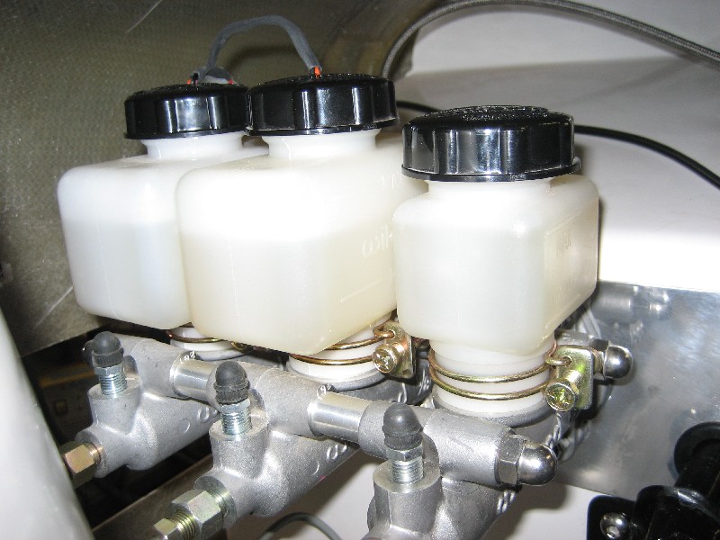
The float switch can now be wired up to the idiot light on your dash. If you are running two switches connect them in parrallel.
Hope this helps
Cheers


 Threaded Mode

