 
 Main Menu
|
|
Nevada Classics
|
|
Advertise at CC
|
| S |
M |
T |
W |
T |
F |
S |
| |
|
|
1 |
2 |
3 |
4 |
| 5 |
6 |
7 |
8 |
9 |
10 |
11 |
| 12 |
13 |
14 |
15 |
16 |
17 |
18 |
| 19 |
20 |
21 |
22 |
23 |
24 |
25 |
| 26 |
27 |
28 |
29 |
30 |
|
|
|
|
CC Advertisers
|
|
 2Likes 2Likes
-
 2
Post By patty442
2
Post By patty442

08-16-2019, 03:45 PM
|
|
Club Cobra Member

|
|
|
Join Date: Mar 2002
Location: arroyo grande, ca,
ca
Cobra Make, Engine: NAF 427
Posts: 1,775
|
|

 Not Ranked
 427 Cobra rear suspension and Spicer half shafts
I have a number of questions about the 427 Cobra rear suspension and the Spicer half shafts.
So here goes:
1) The vertical distance between the rear upper control arm and the rear lower control arm inner mounts on the frame is about 9.5. Right?
2) The vertical distance between the rear upper control arm and the rear lower control arm outer mounts on the upright is about 12.5. Right?
3) So the upper control arms and the lower control are not parallel. Right?
4) With the car at rest, is the lower control arm parallel to the ground?
5) If not, what is its angle?
6) If the lower control arm is parallel to the ground, the upper control arm would slope upwards 3 to the upright.
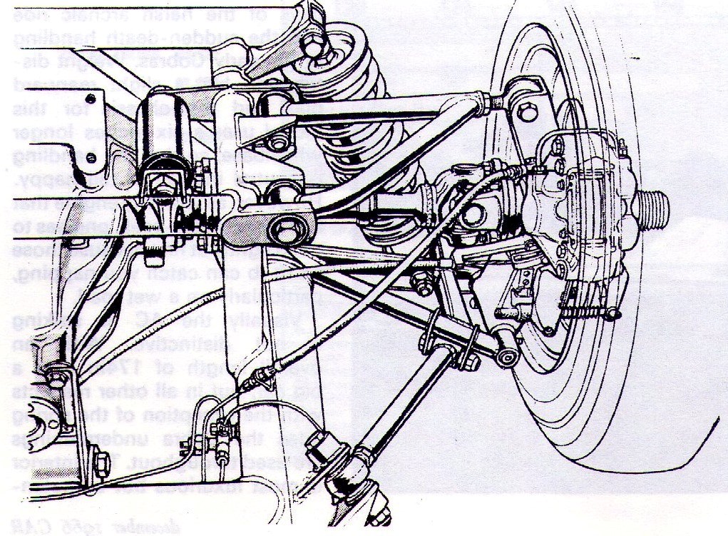
7) In this old rear suspension drawing 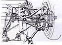
it appears the Spicer half shaft has the slip yoke(internal splines) on the inboard (diff) side and the splined shaft(external splines) on the outboard (upright) side. Is this correct?
I ask because all the Spicer literature Ive read suggests the slip yoke is usually used on the outboard side, a reverse of what is used on the 427 Cobra. Anyone know why?
8) If the lower control arm is parallel to the ground while at rest, that would make the half shaft slope upwards to the upright about 3 like the upper control arm. Right?
9) How much slip takes place in the Spicer half shaft during up (est. 2) and down (est. 2) motion of the rear suspension. Im guessing about 1/2". Close?
If anybody can set me straight on all this I would appreciate it.
Cheers
Greg

|
08-19-2019, 03:01 AM
|
 |
CC Member
|
|
|
Join Date: Jun 2000
Location: Cape Town, South Africa/Mainz, Germany,
Posts: 1,600
|
|
Not Ranked
Maybe this helps:
1): closer to 10", as you know all sits at an angle. UCA 3.5 deg. From CR drawings.
2): 12.38" CSX 4000
3): right
4): I would say, no. Depends on your wheel diameter and ground clearance.
The spindle in the upright is at 6.75" above the LCA mount. This brings your outer lower LCA point to: 27.5" wheel / 2, minus 6.75" = 7" above ground. This is dictated by the wheel diameter.
Your ground clearance (to chassis) works out to be 5" (perhaps 4").
The rear inner LCA mount sits sort of 1.5" higher = 6.5" above ground.
Assuming 5" ground clearance, then your differential/axle shaft outlet is 5" + 2" + 5.25" above ground = 12.25"
The center of your 27.5" wheel is 13.75" above ground, which results in 1.5" higher than the axle shaft.
I am curious myself about 9) But this can be calculated using a triangle function.
We need the length of the axle shaft. It's more like 1 mm only.
__________________
If I don't respond anymore, that's because I can't log in
Last edited by Dominik; 08-19-2019 at 03:10 AM..
Reason: more info
|
08-19-2019, 12:26 PM
|
|
Club Cobra Member
|
|
|
Join Date: Mar 2002
Location: arroyo grande, ca,
ca
Cobra Make, Engine: NAF 427
Posts: 1,775
|
|
Not Ranked
Thanks Dominik. Great info.
But I'm not sure what you did here:
"Assuming 5" ground clearance, then your differential/axle shaft outlet is 5" + 2" + 5.25" above ground = 12.25""
I understand hat 5" is the ground clearance.
What is the 2" and 5.25"?
You're probably wondering what the heck I'm up to.
I'm going down the path that Tom started in a previous posting to use a Corvette C3 differential in a 427 Cobra chassis.
My car is a replica and I am scratch building an IRS for it (just because I like doing that stuff) and wanted help confirming the dimensions.
Another question though.
The Cobra uprights appear to have some castor built in to the UCA mount, but a heim (spherical) joint up there would probably wipe out any castor.
What castor does the 427 Cobra rear upright run at?
I'm about 3/4s done the mock up of the IRS and should have it done in a couple of weeks.
Thanks again for all your help.
Cheers
Greg
|
08-19-2019, 12:37 PM
|
|
Club Cobra Member
|
|
|
Join Date: Mar 2002
Location: arroyo grande, ca,
ca
Cobra Make, Engine: NAF 427
Posts: 1,775
|
|
Not Ranked
oh yeah. I forgot to ask about the Spicer half sahfts.
Am I right that on the Cobra the slip yoke (internal splined) goes inboard on the diff side and the yoke shaft (external splined) goes outboard to the upright?
Even though Spicer typically identifies the slip yoke (internal splined) as the outboard component.
Just wondering?
Cheers
Greg
|
08-20-2019, 01:35 AM
|
|
CC Member
|
|
|
Join Date: Jun 2000
Location: Cape Town, South Africa/Mainz, Germany,
Posts: 1,600
|
|
Not Ranked
Quote:
Originally Posted by my427cobra

Thanks Dominik. Great info.
But I'm not sure what you did here:
"Assuming 5" ground clearance, then your differential/axle shaft outlet is 5" + 2" + 5.25" above ground = 12.25""
I understand hat 5" is the ground clearance.
What is the 2" and 5.25"?
You're probably wondering what the heck I'm up to.
I'm going down the path that Tom started in a previous posting to use a Corvette C3 differential in a 427 Cobra chassis.
My car is a replica and I am scratch building an IRS for it (just because I like doing that stuff) and wanted help confirming the dimensions.
Another question though.
The Cobra uprights appear to have some castor built in to the UCA mount, but a heim (spherical) joint up there would probably wipe out any castor.
What castor does the 427 Cobra rear upright run at?
I'm about 3/4s done the mock up of the IRS and should have it done in a couple of weeks.
Thanks again for all your help.
Cheers
Greg
|
The addition of: 5" (ground clearance) + 2" (from center of chassis) + 5.25" (to diff / axle shaft center) above ground = 12.25"" is the position from ground of the center of your axle shaft as they are coming out of the differential.
Makes sense? This is from the Cobra Restorers drawings.
Kirkham once posted their ground clearance, which you may want to find and use. Else the 5" shouldn't be far off.
I am still struggling to log in, but I am sure you won't be stranded without my input :-)
On a side note:
Looking from above your rear upright will turn/twist during suspension movement. This is to help corner entry and exit.
Racing Cobras have this eliminated. Their suspension movement is limited and this "bump steer(!)" has no noticeable effect.
It is mandatory to keep it at bay for a street car. Not so much the bump steer itself, which you can't really change, but the static toe setting at ride height. And for this your ride height must be correct...
Did I hear Tom's Motorsport in Vegas who set up Cobras since ever? Look them up?
Or find "Morris" here. He has two brains when it comes to Cobras!
__________________
If I don't respond anymore, that's because I can't log in
|
08-20-2019, 07:19 AM
|
|
Club Cobra Member
|
|
|
Join Date: Mar 2002
Location: arroyo grande, ca,
ca
Cobra Make, Engine: NAF 427
Posts: 1,775
|
|
Not Ranked
Thanks Dominik. You've been a great help.
I plan to set the static toe-in by shimming the LCA at the inner mount.
And to set the static camber, by adjusting the heim (spherical) joint at the UCA at the top of the upright.
I might even figure a way to adjust the anti squat by some adjustment at the UCA inner mount.
Cheers
Greg
Last edited by my427cobra; 08-20-2019 at 07:31 AM..
|
08-20-2019, 07:11 PM
|
|
CC Member
|
|
|
Join Date: Dec 2010
Cobra Make, Engine:
Posts: 57
|
|
Not Ranked
Greg, even though you, years ago grouped me with resident experts, I might have something maybe, maybe not that can help you along. Kopec said give you a hand. In about 1969 Sam Feinstein, SCCA A production national Champion in 1973 was upset with the cost of rebuilding his original Cobra differentials as he tore them up racing. His engineers developed an adapter bracket and set up to install a Corvette C2-3 1965 to 1972 or three complete rear differential into the stock factory pick up points of CSX3009 his car at the time. Repairs and parts for the Corvette rear were a fraction of the original Cobra parts. The Corvette rear was finally modified by Tom's differential and required only routine maintainence with no breakage after that. That rear was in his car in the Atlanta runoff's in 1973, where he was awarded the National Championship after the race winning Owens Corning Corvette was disqualified do to an illegal carb spacer. I was there. I have the adapter , hardware, and differential. The jig to create the adapter on the bench was made from CSX3140 where the entire rear frame was gutted from the car. If you need photos tell me. Bob
|
08-21-2019, 07:16 AM
|
|
Club Cobra Member
|
|
|
Join Date: Mar 2002
Location: arroyo grande, ca,
ca
Cobra Make, Engine: NAF 427
Posts: 1,775
|
|
Not Ranked
Bob. Thanks for reaching out with this info.
Please PM me.
Cheers
Greg
|
08-31-2019, 10:40 AM
|
|
CC Member
|
|
|
Join Date: Jun 2015
Cobra Make, Engine:
Posts: 119
|
|
Not Ranked
Did up a couple of drawings show the movement in the half shaft length it’s approximate 3/16 of an inch with the up-and-down wheel movement but I cannot upload any pictures I don’t know what I’m doing wrong or if there’s something wrong with the web-page
Tom
Last edited by Tjd; 08-31-2019 at 10:44 AM..
|
09-01-2019, 07:06 AM
|
|
Club Cobra Member
|
|
|
Join Date: Mar 2002
Location: arroyo grande, ca,
ca
Cobra Make, Engine: NAF 427
Posts: 1,775
|
|
Not Ranked
Hi Tom. That's what I would expect for movement.
I'll send you a couple of pics later today of my version of your adapter mocked up with my attachment points for the UCA and LCA.
Did you get my template in the mail?
e-mail me and we can talk next week.
Cheers
Greg
|
09-09-2019, 09:24 PM
|
|
CC Member
|
|
|
Join Date: Jun 2015
Cobra Make, Engine:
Posts: 119
|
|
Not Ranked
Trying to load some images of the movement of this half shaft showing the difference in length will not let me post Image
Tom
|
09-12-2019, 04:49 PM
|
 |
CC Member
|
|
|
Join Date: May 2008
Location: Brisbane,
QLD
Cobra Make, Engine:
Posts: 2,797
|
|
Not Ranked
3/16 of an inch could be acceptable with the wheels hanging.
What is the endfloat with the shafts EXACTLY horizontal, since this will be where minimum endfloat occurs?
You cannot have zero endfloat at any point, otherwise parts failure will occur.
Gary
|
11-03-2019, 02:26 PM
|
|
Club Cobra Member
|
|
|
Join Date: Mar 2002
Location: arroyo grande, ca,
ca
Cobra Make, Engine: NAF 427
Posts: 1,775
|
|
Not Ranked
This was a great thread. I learned a lot from all of you who contributed as I collected the info I needed to proceed with my IRS scratch build.
To summarize, here are the key specs/dimensions I learned about the 427 Cobra IRS:
Rear Upper Control Arm (UCA) length: 11.4” to 11.5”
Rear Lower Control Arm (LCA) length: 12.4” to 12.5”
Vertical distance between the UCA and LCA at the inner (frame) mounts: 10 to 10.5” (dependent on the UCA downward slant towards the rear for anti-dive)
Rear Upright/bearing carrier total height between the UCA and LCA mounts: 12.35” to 12.43”
Rear UCA mount on the upright to the axle C/L: 6.73”
Rear LCA mount on the upright to the axle C/L: 5.62”
To summarize the rear set-up specs:
Assume a 5” ground clearance (at the rear of the frame) with 15” wheels/27” OD tires
Rear Toe-in: 3/16”
Rear Camber : -1.25 deg
Rear Upright Castor: ?
Rear Anti squat: UCA 3.5 deg (UCA frame mount slopes downward to the rear) LCA 0 deg
So the only remaining question I have for those that have helped me so far:
What amount of static Castor is built into the rear uprights?
Thanks to all who have helped me out.
Cheers
Greg
|
 Posting Rules
|
You may not post new threads
You may not post replies
You may not post attachments
You may not edit your posts
HTML code is Off
|
|
|
All times are GMT -7. The time now is 12:19 PM.
Links monetized by VigLink
|


 Linear Mode


