Welcome to Club Cobra! The World's largest
non biased Shelby Cobra related site!
- » Representation from nearly all
Cobra/Daytona/GT40 manufacturers
- » Help from all over the world for your
questions
- » Build logs for you and all members
- » Blogs
- » Image Gallery
- » Many thousands of members and nearly 1
million posts!
YES! I want to register an account for free right now!
p.s.: For registered members this ad will NOT show
 
 Main Menu
|
|
Nevada Classics
|
|
Advertise at CC
|
|
April 2026
|
| S |
M |
T |
W |
T |
F |
S |
| |
|
|
1 |
2 |
3 |
4 |
| 5 |
6 |
7 |
8 |
9 |
10 |
11 |
| 12 |
13 |
14 |
15 |
16 |
17 |
18 |
| 19 |
20 |
21 |
22 |
23 |
24 |
25 |
| 26 |
27 |
28 |
29 |
30 |
|
|
|
|
CC Advertisers
|
|

02-10-2008, 07:02 PM
|
 |
CC Member

|
|
|
Join Date: Apr 2006
Location: Mildura,
vic
Cobra Make, Engine: FFR Coupe, 416ci of LS goodness
Posts: 2,349
|
|

 Not Ranked
You should be proud of yourself Mike, your work looks amazing.
__________________
Powered by Cu
|
-
Advertising

02-10-2008, 07:44 PM
|
 |
CC Member
|
|
|
Join Date: Jan 2004
Location: Gold Coast,
AUS
Cobra Make, Engine: Wish I had my own PACE 427
Posts: 2,145
|
|
Not Ranked
Do your best Mike.  I was certainly looking forward to seeing your car in the flesh for the first time at this Shelby Fest. |
02-10-2008, 08:01 PM
|
 |
CC Member
|
|
|
Join Date: Jan 2001
Location: Sunbury,
VIC
Cobra Make, Engine: Rat Rod Racer, LS1 & T56
Posts: 5,391
|
|
Not Ranked
I haven't given up yet. I just spoke to the guy building my wheels and he reckons they will be finished and ready to go today.
Cheers
__________________
Mike Murphy
Melbourne Australia
|
02-11-2008, 11:38 PM
|
|
CC Member
|
|
|
Join Date: Jan 2001
Location: Sunbury,
VIC
Cobra Make, Engine: Rat Rod Racer, LS1 & T56
Posts: 5,391
|
|
Not Ranked
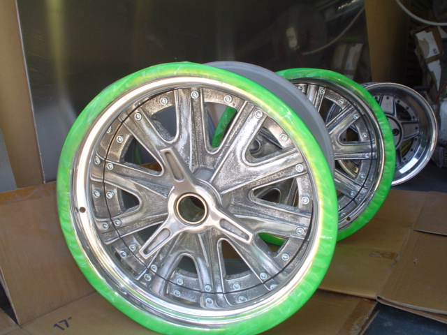
Peter from Ozwheel just sent me a couple of pics of my new rear wheels. Hopefully I should have them by Thursday.
It's only 50mm more dish than the old setup but I reckon it makes quite a difference in the look. The spinner is almost all inside the wheel now and not sticking out like Ben Hur's Charriot.
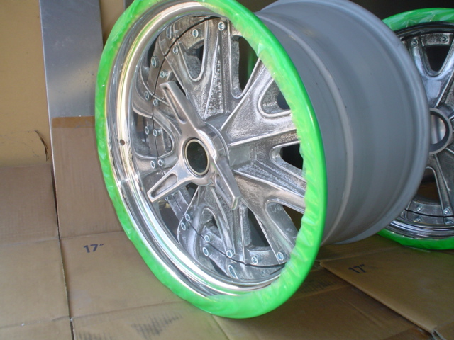
I ordered them with the centers un coated as I plan to get all 4 centers recoated together and wanted them all to match.
Cheers
__________________
Mike Murphy
Melbourne Australia
|
02-12-2008, 04:12 AM
|
 |
CC Member
|
|
|
Join Date: Jan 2007
Location: Sydney,
NSW
Cobra Make, Engine: DRB. Engine out :)
Posts: 517
|
|
Not Ranked
 wooooo
Awsome wheels Mike they look magic.
what colour are they going to be
__________________
"I'd open my mind, but I don't want the stupid to corrupt it." 
|
02-12-2008, 04:32 AM
|
|
CC Member
|
|
|
Join Date: Jan 2001
Location: Sunbury,
VIC
Cobra Make, Engine: Rat Rod Racer, LS1 & T56
Posts: 5,391
|
|
Not Ranked
The centers are going to be HPC coated silver the same as the side pipes.
I restored Garrett's (Justbetter)wheels a little while back. I stripped them down and had the rims re polished and sent the centers away to be HPC coated. They came up magic. Probably as close as you'll get one of these cast centers to looking like polished aluminum.
I'll see if I took a pic of them. Otherwise I'll call in and see Garrett and snap a pic. I think he's using them as a fancy coffee table 
Cheers
__________________
Mike Murphy
Melbourne Australia
|
02-13-2008, 05:33 AM
|
|
CC Member
|
|
|
Join Date: Jan 2001
Location: Sunbury,
VIC
Cobra Make, Engine: Rat Rod Racer, LS1 & T56
Posts: 5,391
|
|
Not Ranked
Well I had an interesting evening in the shed. I decided since I had one side all together that I should see if my geometry theories were going in the right direction.
I built a Bump steer guage to check what the rear end is really doing. The guage uses 2 dial indicators spaced 600mm apart. This is roughly the diameter of a tyre. To measure the bump steer I moved the suspension up 10mm at a time and calculated the difference between the readings on the 2 dial indicators. This shows how much the rear upright is rotating. I then put all the data in an excell spread sheet that let me calculate the change in toe in mm
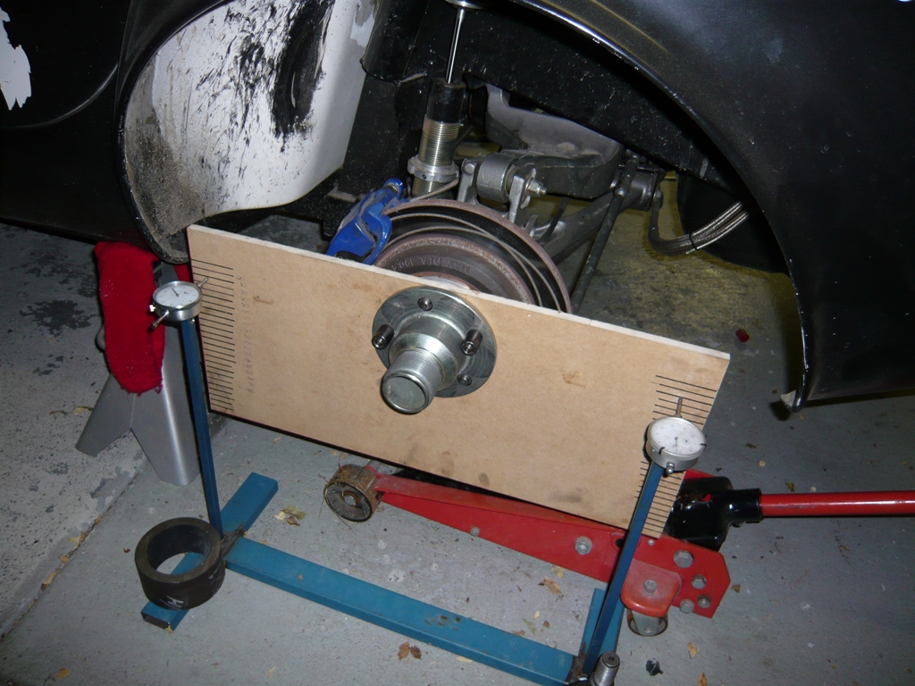
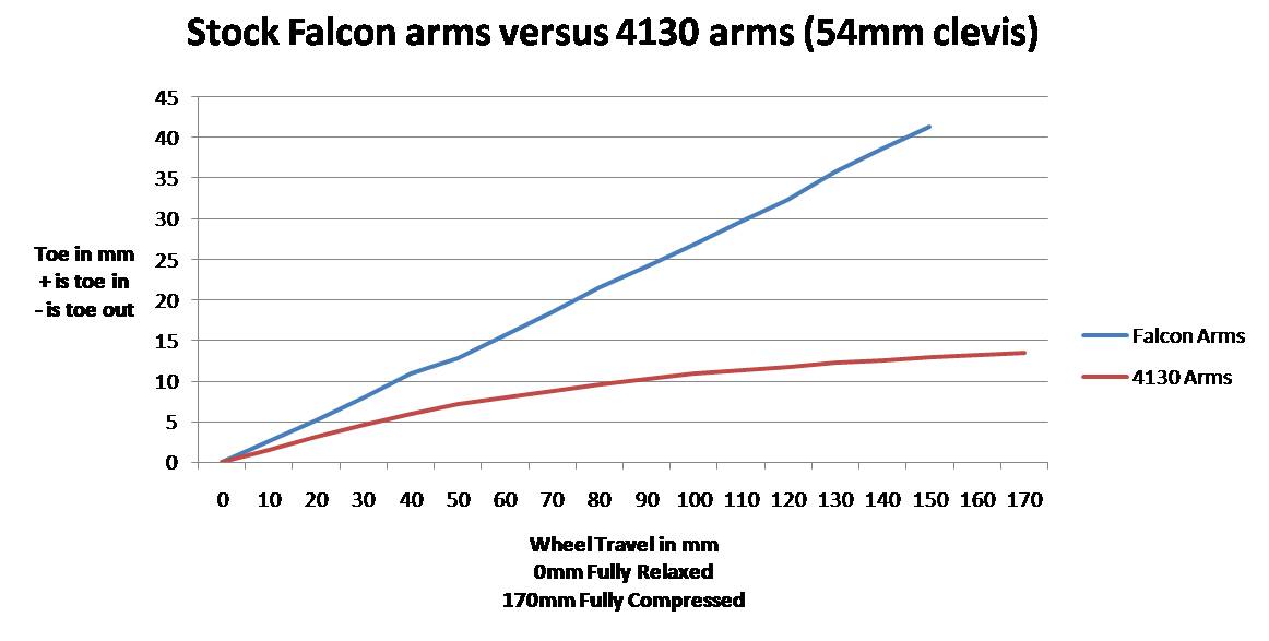
I first measured the rear bump steer on the stock setup with the donor Falcon arms to see how much toe in they added as the suspension compressed. I was shocked to see about 41mm of toe in added from fully relaxed to fully compressed. It's no wonder my tyres keep rubbing on the inner tub as the suspension compresses.
Next I measured my chrome molly arms with the Murphy track locator. On my first pass I the rear suspension went from zero toe to 14mm of toe in from relaxed to compressed. A definite improvement plus I also gained 20mm in wheel travel with the new setup.
This graph shows the comparison between the stock setup and the 4130 arms with a 54mm clevis.
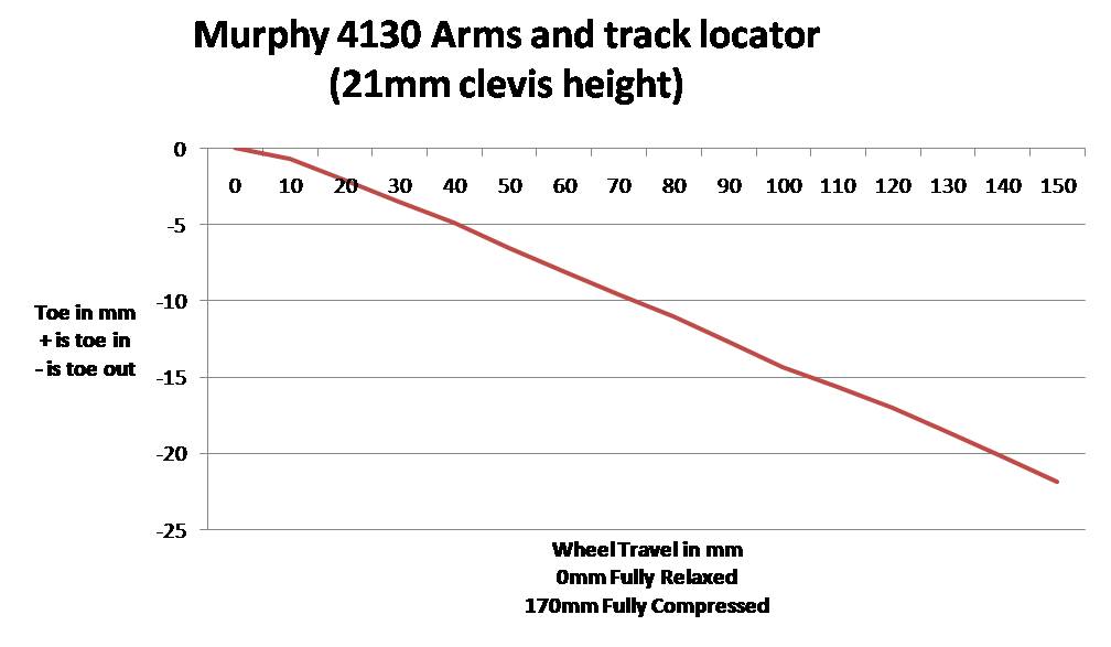
I designed the rear bump steer to be adjustable by changing the height of the rod end where it attaches to the clevis on the upright. My initial setup has a 54mm clevis length so I thought I'd try a shorter length to see what happens. I set it at 21mm and ran the measurments again. The results were horrible with 22mm of toe out being added from relaxed to compressed. Well it proves the adjustment works at least.
Here's the graph
OK how about a length somewhere in between. I tried 41mm next and measured the bump. This time it only added 7mm of toe out when fully compressed. I'm heading in the right direction.
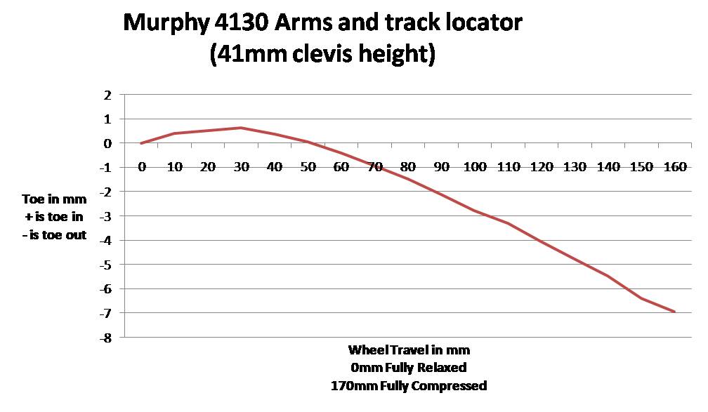
It was getting to late to try another clevis length but I reckon about 48mm will be about spot on.
It's all good fun and I'm learning heaps.
Cheers
__________________
Mike Murphy
Melbourne Australia
Last edited by Aussie Mike; 02-13-2008 at 05:35 AM..
|
02-13-2008, 12:03 PM
|
 |
CC Member
|
|
|
Join Date: Nov 2004
Location: Sydney,
NSW
Cobra Make, Engine: Classic Revival #3199. 366ci L76, T56 6 speed, Blue circle custom paint, Australias most original cobra 2009-2010
Posts: 2,396
|
|
Not Ranked
Mike - these results look fantastic, very exciting stuff for us CR guys. Cant wait to hear your driving impressions with the new setup.
Genius!
Cheers
__________________
Proudly registered since 2013.
|
02-13-2008, 01:19 PM
|
 |
CC Member
|
|
|
Join Date: Feb 2002
Location: Alice Springs, central Australia,
NT
Cobra Make, Engine: Classic revival kit (CR3181), gen III engine, T56 6 speed box, AU XR8 lsd diff
Posts: 5,699
|
|
Not Ranked
Great to see Mike, I am another of the CR guys sitting and watching with Tenrocca.
__________________
Cruising in 5th

---------------------------------------------
Never be afraid to do something new, Remember, Amateurs built the Ark: Professionals built the Titanic.
|
02-13-2008, 01:23 PM
|
 |
CC Member
|
|
|
Join Date: Feb 2006
Location: Paradise Point,
Qld
Cobra Make, Engine: Absolute Pace
Posts: 1,205
|
|
Not Ranked
A whole new level.
Mike,
I read trhis post about 10 times this morning.
Absolutely fantastic.
When you finally produce the Murphy Kit Cobra, you have my order.
Phil
__________________
Not all driveways reach the street!
|
02-13-2008, 03:15 PM
|
|
CC Member
|
|
|
Join Date: Dec 2003
Location: Gurnee,
IL
Cobra Make, Engine: Kirkham #259
Posts: 1,396
|
|
Not Ranked
Mike
Do you think there's a reason that control arms are Straight from the upper chassis pick up point to the upright????
And bump steer needs to be .015"thousands of an inch per inch of travel...... from ride height in a bump or droop situation.
And not on a piece of wood...... not flat and accurate......
Don't mean to bust your bubble.... but if you are going to do what you are doing .....get it accurate or you may hurt yourself.
The bump steer can be controlled by rotating the upright...... and your upper control arm would have me concerned if you have any power applied to the rear wheels and they have any grip.......
Just some thoughts....
Morris
__________________
Morris
|
02-13-2008, 04:10 PM
|
|
CC Member
|
|
|
Join Date: Jan 2001
Location: Sunbury,
VIC
Cobra Make, Engine: Rat Rod Racer, LS1 & T56
Posts: 5,391
|
|
Not Ranked
Hi Morris, Thanks for the input. I apreciate your thoughts as you seem to have done a lot of research into car setup yourself.
I don't quite inderstand what you mean about the upper control arms? Unfortunately they have to have a curve in them to clear the upper chassis rails. The original cast steel Ford arms are curved also. I had thought of notching the chassis rails to run straight arms but I wanted a bolt in solution.
The majority of the suspension loads are taken through the lower arm and I think the upper arm will be more than strong enough. It's made from 1.5" x 0.120" wall 4130 tube. The only mod I've been thinking on is a bar between the 2 legs to complete the "A" but I'm not sure it's nescesary since the legs on the upper arm are quite short. As far as putting HP through it I think the brackets on the chassis would colapse before the upper arm bent.
I have a friend in the engineering department of one of the local universities and he's offered to do some finite element analysis calcs on the arms. I'll probably take him up on it.
The bump measurements I've done so far are just to get an idea of how it's going. I've got a sheet of 6mm aluminium plate that I've got to finish machining to replace the craft wood. I'm also putting together some revised uprights for the dial indicators that will let me raise and lower the whole stand. This will let me set the suspension at ride height and work back and forth from there.
The rear end problems I've been feeling on the track are now fairly evident from the numbers. When the local tyre shop does the rear wheel alignment he sets the rear toe to 2mm at ride height. If we take it that ride height is 1/2 of the suspension travel then at full droop the car will have about 18mm of toe out on the rear. When I lift on the main straight at Winton and shift back to 3rd for the left hand kink the rear end feels quite squirmy (that's a technical term  ). I believe this is because as I decelerate and shift down the weight transfers to the front and subsequent lift of the rear means I have toe out. I stiffened up the damping on all the shocks and this settled down a bit but it's still there. The stiffer shocks reduce the weight transfer and keep the rear from lifting but its a band-aid solution. The real fix is to tune the bump steer out which is what I'm trying to do.
So from your reccomendation of 0.015" of bump per inch of travel I'm aiming for about 2.5mm of toe change over the whole suspension travel. Is that the maximum reccomended or minimum? should I try to tune it to less than that if possible?
I can see some argument for having a bit of bump in there. e.g: As the car pitches into the corner the outside rear wheel turns in slightly and helps turn the rear of the car. What do you think?
Cheers
__________________
Mike Murphy
Melbourne Australia
|
02-14-2008, 09:15 AM
|
|
CC Member
|
|
|
Join Date: Dec 2003
Location: Gurnee,
IL
Cobra Make, Engine: Kirkham #259
Posts: 1,396
|
|
Not Ranked
Mike
When you start trying to push 700-800 Hp thru to the rear tires the upper control arm will come into play moving the car in a forward and aft drive.
So the side force along with the forward bite will put a strain on the upper control arm........ and the issue is flexing of the upper control arm..... which would change the geo of the rear suspension.... even thought bent control arms are used to get around frames and other componets ...... the line is still theoretically straight ...but the arm is going to bend more or less .....as opposed to a straight arm.....
And yes the .015"thousands per inch is max allow and if you can get it better it's always desired.
You are right on the mark with the rear end getting loose on you when hitting the brakes at the end of a straight .....as the geometry moves from a Toe-in condition to a Toe-out condition which is a wandering condition......
Toe-in is what you want on the rear end ..... you want the car to track like it should and not go from a Toe-in to toe-out and back condition as the back end will move around from side to side......and this has been a issue with these cars since they were made...... Many folks will set so much toe-in so they don't go into toe-out and then they have just scrubbed alot of speed.
Unstable suspension geometery will cause many ill-effects to the handling of a chassis.
Morris
__________________
Morris
|
02-17-2008, 01:45 AM
|
|
CC Member
|
|
|
Join Date: Jan 2007
Location: Sydney,
NSW
Cobra Make, Engine: DRB. Engine out :)
Posts: 517
|
|
Not Ranked
are we there yet
are we there yet , are we going , how long, are we going to Winton,when is it gonna be ready, will it take long, should we start packing,
Just muck'n around.
So will u be there, lol
how close are ya.
__________________
"I'd open my mind, but I don't want the stupid to corrupt it."
|
02-17-2008, 03:05 AM
|
|
CC Member
|
|
|
Join Date: Jan 2004
Location: Gold Coast,
AUS
Cobra Make, Engine: Wish I had my own PACE 427
Posts: 2,145
|
|
Not Ranked
Only 5 more sleeps to Shelby Fest. That's if Mike will actually be getting any sleep before then.  |
02-20-2008, 04:43 AM
|
|
CC Member
|
|
|
Join Date: Jan 2007
Location: Sydney,
NSW
Cobra Make, Engine: DRB. Engine out :)
Posts: 517
|
|
Not Ranked
2 sleeps
2 More ....................................
__________________
"I'd open my mind, but I don't want the stupid to corrupt it."
|
02-20-2008, 02:57 PM
|
|
CC Member
|
|
|
Join Date: Jan 2001
Location: Sunbury,
VIC
Cobra Make, Engine: Rat Rod Racer, LS1 & T56
Posts: 5,391
|
|
Not Ranked
Looks like I'll be enjoying Shelbyfest from the sidelines this year. There's just not enough hours in the day.
I'm kind of looking forward to watching the cars this year and waving my video camera around.
If anyone needs a hand with a spanner on the week end just yell out.
Cheers
__________________
Mike Murphy
Melbourne Australia
|
03-04-2008, 06:07 AM
|
|
CC Member
|
|
|
Join Date: Jan 2001
Location: Sunbury,
VIC
Cobra Make, Engine: Rat Rod Racer, LS1 & T56
Posts: 5,391
|
|
Not Ranked
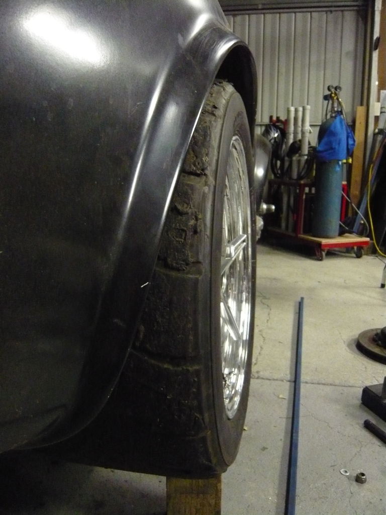
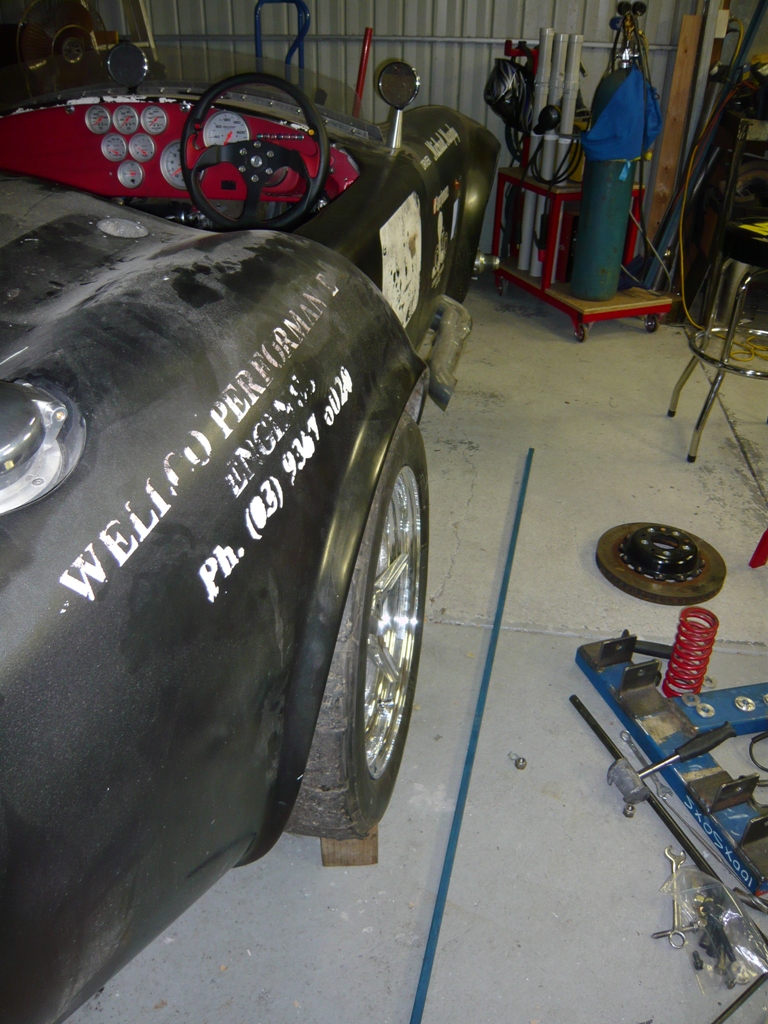
Had a bit of time off from the Cobra and caught up on some jobs round the house. I got back to it the other night and bolted up my new wheels for a look see.
My offsets worked out just how I wanted. The wheel tucks up under the guard nicely. While it's close in places with the square shouldered race tyre nothing should rub through the whole wheel travel.

The spinner is completely inside the wheel now. I'd grown to like the Ben Hurr look to I was in two minds when I first bolted the new wheel on. I'm growning to like it now.
Looks like I'll need to throw another $20 worth of flat black at the car before I take it out again. All the stickers from the Winton 6 Hour peeled the spit thin layer of black paint off.
I reckon I'll pull the body before the nationals and paint the underside and the engine bay properly and then it can be bolted down for the last time. It'll be flat black for some time but I'll finish doing the prep on the body so at least it's all nice and smooth.
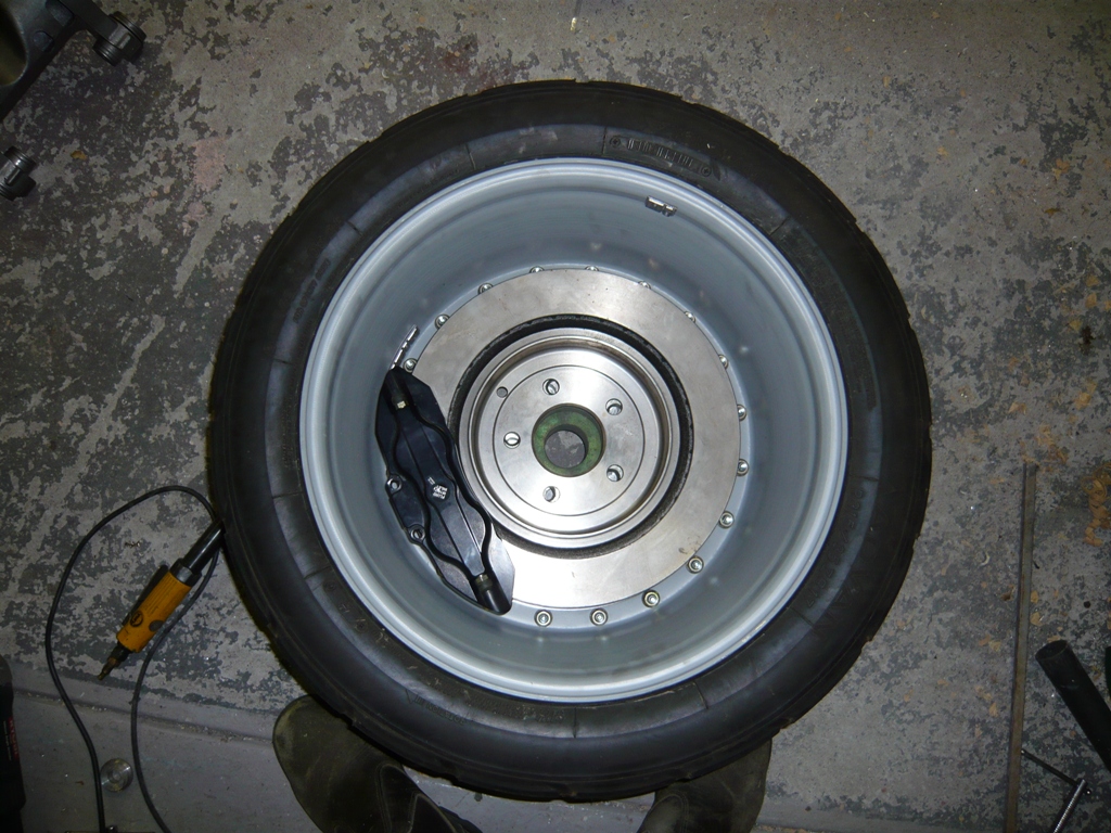
Another thing I'm happy about my new wheels is I now have clearance for my big rear brakes. I asked the wheel builder to machine a bit more clearance on the spokes and set them up with a more clearance from the mounting boss to the back of the spokes. The HiSpec rear calipers clear with room to spare. The new discs measure 328mm x 26mm and should really help pull it up.
After trying out the awesome brakes on the Mizzi Missile at Shelby Fest I can't wait to get them working.
Cheers
__________________
Mike Murphy
Melbourne Australia
|
03-04-2008, 01:27 PM
|
 |
CC Member
|
|
|
Join Date: Aug 2001
Location: Melbourne, Australia,
Vic
Cobra Make, Engine: G-Force Mk I, 5L Windsor, TKO 600, enhanced Jag / Koni suspension & LSD Diff.
Posts: 2,304
|
|
Not Ranked
Mike
Are your rims all Ali, or do they have bolt in steel centres?
What's normal for the good rims?
Cheers
__________________
slowy
|
03-04-2008, 04:17 PM
|
|
CC Member
|
|
|
Join Date: Jan 2001
Location: Sunbury,
VIC
Cobra Make, Engine: Rat Rod Racer, LS1 & T56
Posts: 5,391
|
|
Not Ranked
Hi Slowy,
The rims are alloy. They are a 3 piece design. The 2 rim halves are spun from aluminium sheet. It's a neat machine to watch when they are being made.
The ring of bolts run through the 2 rim halves and the wheel center and clamp the whole thing together. Theres a bead of silicon sealer run round between the rim halves to seal everything. I also got my rim halves welded together for a bit of extra strength.
Cheers
__________________
Mike Murphy
Melbourne Australia
|
 Posting Rules
|
You may not post new threads
You may not post replies
You may not post attachments
You may not edit your posts
HTML code is Off
|
|
|
All times are GMT -7. The time now is 09:28 PM.
|
|


 Linear Mode


