Absolute Pace

Go Back   Club Cobra > Club Forums > Australian Cobra Club

Welcome to Club Cobra!  The World's largest non biased Shelby Cobra related site!

  •  » Representation from nearly all Cobra/Daytona/GT40 manufacturers
  •  » Help from all over the world for your questions
  •  » Build logs for you and all members
  •  » Blogs
  •  » Image Gallery
  •  » Many thousands of members and nearly 1 million posts! 

YES! I want to register an account for free right now!  p.s.: For registered members this ad will NOT show

Keith Craft Racing
Nevada Classics
Main Menu
Nevada Classics
Nevada Classics
MMG Superformance
MMG Superformance
Advertise at CC
Banner Ad Rates
Keith Craft Racing
MMG Superformance
March 2024
S M T W T F S
          1 2
3 4 5 6 7 8 9
10 11 12 13 14 15 16
17 18 19 20 21 22 23
24 25 26 27 28 29 30
31            
  #1 (permalink)  
Old 12-02-2007, 06:31 PM
Aussie Mike's Avatar
CC Member
Visit my Photo Gallery

 
Join Date: Jan 2001
Location: Sunbury, VIC
Cobra Make, Engine: Rat Rod Racer, LS1 & T56
Posts: 5,391
Not Ranked     
Default CR Rear suspension mods

Hi All,

I thought I'd start a thread to doccument some of the rear suspension changes I'm making to my Classic Revival chassis.

Here's a pic I snapped this morning of the trial fitting of a tubular lower control arm I've been working on. I built a Jig based on the original cast steel AU ford arm. The jig allows me to buld a lower arm in original length or 50mm shorter. Narrowing the rear end 50mm on each side will give me a bit more dish on the rear wheels and look heaps better.


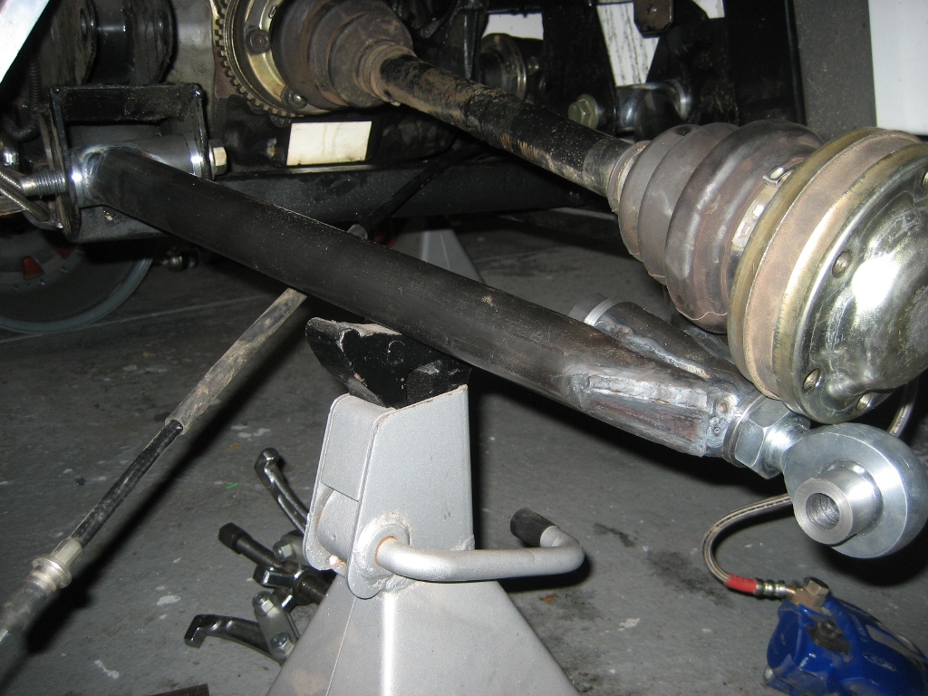
The new arms are made from 4130 Chrome Molly tube and are significantly lighter than the original Ford arms. I'm hoping to cut 30KG out of the rear of the car with this setup. This is all unsprung weight too which should give the shocks and springs a better chance of controling the wheel.

I'm just working out the positioning of the new shock mounts at the moment so the arm will be in and out while I work out where everything should go.

Part of the new design is to remove the bump steer in the rear suspension that is a left over of the Ford design. I should be able to tune it out completely with this setup.

This arm design also alows me to adjust the camber from the bittom of the upright as well as the top. This will help with maintaining the right ammount of plunge on the rear axles.

Cheers
__________________
Mike Murphy
Melbourne Australia


Last edited by Aussie Mike; 12-05-2007 at 06:13 PM..
Reply With Quote
  #2 (permalink)  
Old 12-03-2007, 02:04 AM
Gav's Avatar
Gav Gav is offline
CC Member
Visit my Photo Gallery

 
Join Date: Apr 2006
Location: Mildura, vic
Cobra Make, Engine: FFR Coupe, 416ci of LS goodness
Posts: 2,349
Not Ranked     
Default

Lookin good! One pair in black with red bushings please.
__________________
Powered by Cu
Reply With Quote
  #3 (permalink)  
Old 12-04-2007, 12:42 AM
LoBelly's Avatar
Senior Club Cobra Member
Visit my Photo Gallery

 
Join Date: Feb 2006
Location: Melbourne, VIC
Cobra Make, Engine: RMC, carb 347 TopLoader and Jag running gear ~ so old school I time it with an hour-glass :D
Posts: 1,293
Not Ranked     
Default

Looking good Mike-
A bit more dish on the CRs wont go astray.

No doubt your plans will be popular with the other CR owners

Good thing you dont sleep with there only being a couple of months to ShelbyFest.

LoBelly
Reply With Quote
  #4 (permalink)  
Old 12-05-2007, 03:49 PM
Aussie Mike's Avatar
CC Member
Visit my Photo Gallery

 
Join Date: Jan 2001
Location: Sunbury, VIC
Cobra Make, Engine: Rat Rod Racer, LS1 & T56
Posts: 5,391
Not Ranked     
Default

Another update with a few more pictures.

I tackled one of the more difficult jobs on the rear end modifications. The Axle flanges to adapt the Commodore axles to the Ford Hubs. The Commodore axles are narrower than the Ford and use a bolt up flange. I like these axles because you can just about remove the whole axle without unbolting all the rear suspension. I had made flanges previously when I did the Commodore diff conversion. The new ones had to be 50mm shorter for the narrowed rear end.

Here's the completed axle flange. It's made from an AU falcon axle mated to a Commodore diff flange. There was a lot of machining and setting up to get this together. The material the axle is made from is very hard and my tungsten carbide lathe tooling wouldn't touch it. I ended up having to rig up a tool post grinder to machine it down.


The 2 pieces are TIG welded together inside and out so should be strong enough. There are only drive loads going through the flange as all the suspension and braking loads are taken through the suspension arms.


Bolted to the end of the axle


With the Hub in place


The other thing I like about this setup now is that both CVs (inner and outer)are pretty close to in line with the suspension pivot points.


The next job is the new shock mounts and sway bar attachments.

Cheers
__________________
Mike Murphy
Melbourne Australia


Last edited by Aussie Mike; 12-05-2007 at 03:52 PM..
Reply With Quote
  #5 (permalink)  
Old 12-05-2007, 03:54 PM
sambo's Avatar
CC Member
Visit my Photo Gallery

 
Join Date: Jan 2007
Location: Melbourne, VIC
Cobra Make, Engine: Harrison, 6.0L Chev
Posts: 2,513
Not Ranked     
Default

Mike, I think you might have been an automotive engineer in a past life! Brilliant work and nice pictures too. Good luck with the rest of the conversion.

Paul
Reply With Quote
  #6 (permalink)  
Old 01-14-2008, 12:31 AM
CC Member
Visit my Photo Gallery

 
Join Date: Oct 2007
Location: Darwin, NT
Cobra Make, Engine: Classic Revival Kobra,LS7 427
Posts: 380
Not Ranked     
Default

This is what philm will have to do now he has destroyed the ford set up
Reply With Quote
  #7 (permalink)  
Old 01-14-2008, 05:07 AM
Aussie Mike's Avatar
CC Member
Visit my Photo Gallery

 
Join Date: Jan 2001
Location: Sunbury, VIC
Cobra Make, Engine: Rat Rod Racer, LS1 & T56
Posts: 5,391
Not Ranked     
Default

I don't think this would have saved Phil's diff. He's making some serious mumbo and using drag tyres. That combination finds the weak link in any drivetrain.

The last update disapeared with the new server being installed.

Here's the pics again if any one is interested.

This is the new lower shock mount


The new track locater design that should eliminate the rear bump steer


This one shows the pick up points for the adjustable sway bar setup. The bars will be tubular with aluminum arms. They'll have a row of holes that will corespond with the holes in the arm and the sway bar can be adjusted by moving the links along to the appropriate holes.


I've just about finshed the upper arm. This took a bit of thinking to make something that will clear the upper chassis rails. I've also switched to a urethan bush design as I reckon the nylon bushes might be a little to harsh for the street. The urethan will also have a little give that will let it spring a little rather than pounding out to an oval shape from the changing loads.

Hope to have some pics of the upper arm in the next day or so.

Cheers
__________________
Mike Murphy
Melbourne Australia

Reply With Quote
  #8 (permalink)  
Old 01-14-2008, 09:42 AM
CC Member
Visit my Photo Gallery

 
Join Date: Dec 2003
Location: Gurnee, IL
Cobra Make, Engine: Kirkham #259
Posts: 1,393
Not Ranked     
Default

Mike

Have you calculated the wheel rate........???

The motion ratio of the location of the shock doesn't look to good.....

The shock looks to be only mounted at about the half way point on the lower control arm........

could be the photo that gives it that look.....

Morris
__________________
Morris
Reply With Quote
  #9 (permalink)  
Old 01-14-2008, 03:21 PM
Aussie Mike's Avatar
CC Member
Visit my Photo Gallery

 
Join Date: Jan 2001
Location: Sunbury, VIC
Cobra Make, Engine: Rat Rod Racer, LS1 & T56
Posts: 5,391
Not Ranked     
Default

Hi Morris,

I think it's a bit of an optical illusion with the pictures. The shock mount is as far out as I can get it whilst still maintaining enough clearance to the back of the wheel rim. For wheel rate the ratio is actually better now than the original lower arm setup. I'll have to do a bit of math and work out the difference to the original Ford arms.

Here's a pic of the standard Ford rear end with it's cast steel arms. You can get an idea of the length of the arms and the position of the lower shock mount in relation to the wheel hub. My new setup has the shock in about the same position but the Hub is 2" closer in now.


The lower arms are quite long. My current wheels have a 9.25" back space and 2.875" front space. The Classic Revival chassis doesn't allow for a traditional looking wheel as you can see from this pic.


The new rear wheels have a 7.25" back space and a 4.875" front space.

I hope to achieve 3 main things with these mods. * A huge reduction in unsprung weight. * Eliminating the rear bump steer * Less offset on the rear wheels.

A couple of bonuses are positioning the wheel offsets so the loads are more evenly distributed on the wheel bearing. A better sway bar setup. And the tubular arms look cool.

Cheers
__________________
Mike Murphy
Melbourne Australia


Last edited by Aussie Mike; 01-14-2008 at 03:24 PM..
Reply With Quote
  #10 (permalink)  
Old 01-14-2008, 05:05 PM
boxhead's Avatar
CC Member
Visit my Photo Gallery

 
Join Date: Feb 2002
Location: Alice Springs, central Australia, NT
Cobra Make, Engine: Classic revival kit (CR3181), gen III engine, T56 6 speed box, AU XR8 lsd diff
Posts: 5,699
Send a message via Yahoo to boxhead
Not Ranked     
Default

Quote:
Originally Posted by Aussie Mike
Hi Morris,

And the tubular arms look cool.

Cheers

I agree.
__________________

Cruising in 5th


---------------------------------------------
Never be afraid to do something new, Remember, Amateurs built the Ark: Professionals built the Titanic.
Reply With Quote
  #11 (permalink)  
Old 01-15-2008, 08:25 AM
CC Member
Visit my Photo Gallery

 
Join Date: Dec 2003
Location: Gurnee, IL
Cobra Make, Engine: Kirkham #259
Posts: 1,393
Not Ranked     
Default

Mike

I believe you are on the right track........ and it looks great......

But ..... as you know .... bump steer is controlled by the rotation of the upright...... so locating the upper control arm..... and then having the ability to move it in a fore and aft rotational movement will give you the bump steer that you are looking for..... Matching the two different arc's is where you will have the minimum bump steer.....

Just some thoughts....

Morris
__________________
Morris
Reply With Quote
  #12 (permalink)  
Old 01-18-2008, 01:47 AM
Aussie Mike's Avatar
CC Member
Visit my Photo Gallery

 
Join Date: Jan 2001
Location: Sunbury, VIC
Cobra Make, Engine: Rat Rod Racer, LS1 & T56
Posts: 5,391
Not Ranked     
Default

I'm a bit limited in what I can do by the chassis and the location of the existing mounts. I didn't really want to make any drastic changes to the chassis. So I'm just trying to change things to what I reckon might perform better within the existing mountings.

Currently the big rotation of the upright is a result of the track locator rod (if that's what it's called) working in a different arc to the upper and lower unequal length arms. With this type of setup I think it would be pretty difficult to eliminate all of the bump steer.

With the new setup I'm tying the track locator to the lower arm rather than the chassis. I can still adjust the toe OK and I can tune a certain ammount of bump steer in or out depending on the height I place the pivot point on the upright and how it relates to the pivot where the upright attaches to the lower arm. I can also dial in a lot more negative camber than the stock setup if I need it.

I have to say I'm having fun with all of this and the thought process involved.

Cheers
__________________
Mike Murphy
Melbourne Australia

Reply With Quote
  #13 (permalink)  
Old 01-18-2008, 04:15 AM
CC Member
Visit my Photo Gallery

 
Join Date: Feb 2006
Location: The Hills, NSW
Cobra Make, Engine: Absolute Pace
Posts: 1,354
Not Ranked     
Default

I have serious offset envy Mike!

I wish all of the classic revival cars had a few of inches of dish!

Perhaps the new chassis on the way will address this.

Ben
Reply With Quote
  #14 (permalink)  
Old 01-18-2008, 07:21 PM
Aussie Mike's Avatar
CC Member
Visit my Photo Gallery

 
Join Date: Jan 2001
Location: Sunbury, VIC
Cobra Make, Engine: Rat Rod Racer, LS1 & T56
Posts: 5,391
Not Ranked     
Default

Phil N mentioned he'd been and seen Ians new chassis. Suposedly he's using fabricated suspension rather than donor stuff. Hopefully he'll get on the forum and give us a sneak peek and some info on it.

Cheers
__________________
Mike Murphy
Melbourne Australia

Reply With Quote
  #15 (permalink)  
Old 01-18-2008, 07:47 PM
Aussie Mike's Avatar
CC Member
Visit my Photo Gallery

 
Join Date: Jan 2001
Location: Sunbury, VIC
Cobra Make, Engine: Rat Rod Racer, LS1 & T56
Posts: 5,391
Not Ranked     
Default

I've made a bit more progress this last couple of nights. I've really got to get cracking on it or I won't be ready for Shelby fest. I'm also working up in India for the next couple of weeks so time is short.

Here'a pic of the new lower arm in the jig sitting next to the original arm. The bushings used in the jig are all machined from aluminum and locate all the pieces so they don't move when welding. They arms do spring a little when they come out of the jig so I still have to tweek them a little in the hydraulic press afterwards. I made some fixtures to let me do that accurately.

You can also see in this pic how the shock mout position is about the same place as the original. I've tried to move it in closer to the center line so it doesn't put as much of a twisting force on the arm.


Here's the finished upper arm in it's jig sitting next to the original. This took a bit of thinking to make an arm that would clear the upper chassis rail without having to cut anything.


The upper arm turned out nice and looks pretty cool with it's swoopy curves.


Both Jigs are made from some heavy wall RHS and are designed to make standard length or shortened arms. You wouldn't want to drop one on your toe either as they weigh a ton.

The next thing to sort out is the supension bushes. I've given away the idea of using nylon as I reckon it would pound out into an oval shape over time. I setled on Urethane as it has a little give in it that should make it last.

My local auto parts shop (who I often frequent) kindly let me go over their range of urethane bushes with a vernier caliper looking for something suitable. I finally found some bushes that had about the right dimensions or ID and OD. I made a small fixture that let me clamp the bush in the lathe and then with some very sharp tooling and a fast spindle speed I was able to trim them down to exactly what I wanted. I also machined up some steel sleeves for them to run on and they should work a treat.

The bushes on the right are the original. The ones on the left have been trimmed.


Now I've got to build the arms for the passengers side and paint everything ready for assembly.

Cheers
__________________
Mike Murphy
Melbourne Australia


Last edited by Aussie Mike; 02-03-2008 at 06:55 AM.. Reason: spelling
Reply With Quote
  #16 (permalink)  
Old 01-18-2008, 09:04 PM
CC Member
Visit my Photo Gallery

 
Join Date: May 2002
Location: Brisbane Australia, QLD
Cobra Make, Engine: RMC under re-construction, GenIV with tremec 600, Jag 3.31 L/S diff
Posts: 3,318
Not Ranked     
Default

That's gonna be one nice ride when you're finished Mike.

By the way.... The trick for machining urethane is to put the bushes into the freezer for a few hours prior to turning.

Now....back to the shed to work on my simple jag based ars....ermmmm.....rear end.
__________________
It's impossible to soar like an eagle when you're surrounded by turkeys.
Reply With Quote
  #17 (permalink)  
Old 01-18-2008, 11:48 PM
CC Member
Visit my Photo Gallery

 
Join Date: Oct 2007
Location: Darwin, NT
Cobra Make, Engine: Classic Revival Kobra,LS7 427
Posts: 380
Not Ranked     
Default

I have heard that Ian is using tube for the main chassis rails and VE Commodore rear end set up and VE brakes all round.
Reply With Quote
  #18 (permalink)  
Old 02-10-2008, 06:08 AM
Aussie Mike's Avatar
CC Member
Visit my Photo Gallery

 
Join Date: Jan 2001
Location: Sunbury, VIC
Cobra Make, Engine: Rat Rod Racer, LS1 & T56
Posts: 5,391
Not Ranked     
Default

Time for an update

Well I lost 3 weekends in the shed because I had to go work in India. Things are not looking good for being ready for Shelbyfest.

I made a bit of progress on the weekend. The drivers side is pretty much done bar a coat of paint and final assembly.


I fabricated an upper shock mount to suit the new arms. One thing I found with the shock mount on the standard Ford setup is that the upper arm used to hit the chassis before the shock bottoms out on its bump stop. Maybe it's the 15" AVO shocks I'm running but for the new setup I thought I'd fix it. The new curved upper arm clears the chassis rail all the way and the shock bottoms out on its bump stop with clearance to spare.


I've got to get working on the passengers side arms now. The new rear wheels should hopefully arrive this week too.

Cheers
__________________
Mike Murphy
Melbourne Australia

Reply With Quote
  #19 (permalink)  
Old 02-10-2008, 06:43 AM
LoBelly's Avatar
Senior Club Cobra Member
Visit my Photo Gallery

 
Join Date: Feb 2006
Location: Melbourne, VIC
Cobra Make, Engine: RMC, carb 347 TopLoader and Jag running gear ~ so old school I time it with an hour-glass :D
Posts: 1,293
Not Ranked     
Default

Good Stuff Mike

Fingers crossed for an in-time-for ShelbyFest finish.

LoBelly
Reply With Quote
  #20 (permalink)  
Old 02-10-2008, 01:16 PM
Philm's Avatar
CC Member
Visit my Photo Gallery

 
Join Date: Feb 2006
Location: Paradise Point, Qld
Cobra Make, Engine: Absolute Pace
Posts: 1,205
Not Ranked     
Default What bump steer

Mike,
It looks fantastic.

I hope you make the Shelbyfest.

Phil
__________________
Not all driveways reach the street!
Reply With Quote
Reply


Thread Tools
Display Modes Rate This Thread
Rate This Thread:

Posting Rules
You may not post new threads
You may not post replies
You may not post attachments
You may not edit your posts

BB code is On
Smilies are On
[IMG] code is On
HTML code is Off
Trackbacks are On
Pingbacks are On
Refbacks are On


All times are GMT -7. The time now is 10:33 PM.


Powered by vBulletin® Version 3.8.0
Copyright ©2000 - 2024, Jelsoft Enterprises Ltd.
Search Engine Friendly URLs by vBSEO 3.6.0
The representations expressed are the representations and opinions of the clubcobra.com forum members and do not necessarily reflect the opinions and viewpoints of the site owners, moderators, Shelby American, any other replica manufacturer, Ford Motor Company. This website has been planned and developed by clubcobra.com and its forum members and should not be construed as being endorsed by Ford Motor Company, or Shelby American or any other manufacturer unless expressly noted by that entity. "Cobra" and the Cobra logo are registered trademarks for Ford Motor Co., Inc. clubcobra.com forum members agree not to post any copyrighted material unless the copyrighted material is owned by you. Although we do not and cannot review the messages posted and are not responsible for the content of any of these messages, we reserve the right to delete any message for any reason whatsoever. You remain solely responsible for the content of your messages, and you agree to indemnify and hold us harmless with respect to any claim based upon transmission of your message(s). Thank you for visiting clubcobra.com. For full policy documentation refer to the following link: CC Policy