This is basically nothing more than tapping in to five wires, and then wiring in a switch. The only difference is that you have to put a diode in to the five taps, and you have to wire in a flashing unit. You need to fuse it, too.
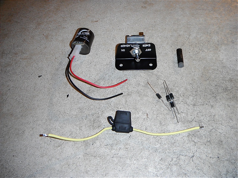
Here are the parts you'll need: Clockwise from upper left -- a flashing unit (electronic), a nice switch (this is a re-pop from the 1966 Mustang glove box switch), Posi-Taps (you'll need three), barrier diodes (you'll need five), in-line spade fuse (10 amp). In all of my pics, I used green wire for this job, and the pictures follow the narrative.
Use a Posi-Tap to tap in to the blue wire heading to your existing flasher (see the Posi-Tap in this pic?). Feed it 12 volts and see if your dashboard light comes on. It should.
Tap in to the green and yellow wires that are heading to the trailer relay that is behine the fast-blow fuse holder. Feed each 12 volts and see if the front and back lights comes on. You have to do this test one wire at a time. If you feed both at the same time, the rear lights will not come on.
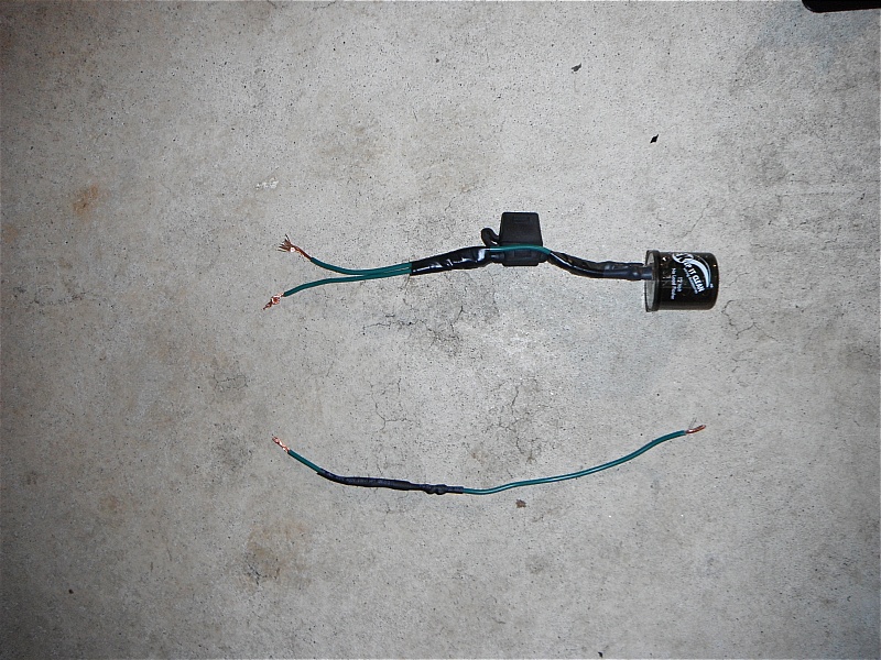
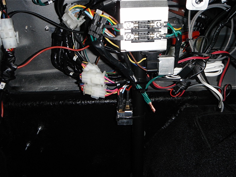
Wire your in-line fuse to your flasher, and solder in your five diodes to five strands of wire making a note to have the little striped end of the diode (which goes to the load side of your circuit) be at an easily recognizable end. On my pics, the shorter end of the wire always will have the load side of the diode.
Place three of the diode wires in to the Posi-Taps, making sure the short "load end" of the diode is headed in the correct direction. Connect the other three ends of your wires together and then test your turn signals and brake signals to see if they are behaving normally. If they are not, then you screwed up the direction of the diodes. Now feed 12 volts to the three ends of the diode wires that are all twisted together. Your dash light should come on and the front turn signals should come on. The rear lights will not come on.
Now attach your remaining two diode wires to the passenger side terminals of the fast-blow fuse holder. Connect the two ends together and feed them 12 volts. Your rear lights should come on.
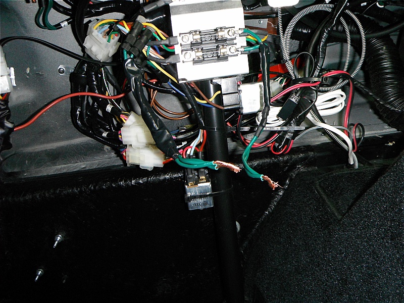
Connect all five wires together. Feed them 12 volts and all five lights (four turn signals and the dash light) should come on. Then leave the five wires twisted together, but without 12 volts feeding it, and check again that your turn signals and brake lights behave normally.
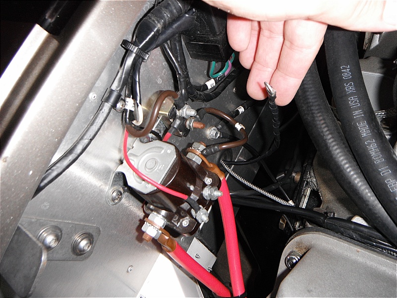
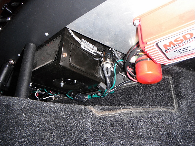
Feed a new line through your firewall below the starter solenoid. Have a ring eyelet on it that will attach to the master 50 amp circuit breaker. This will feed your emergency flasher circuit so that the circuit will work with the key on or off.
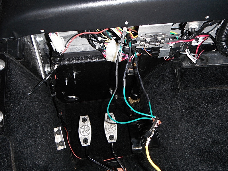
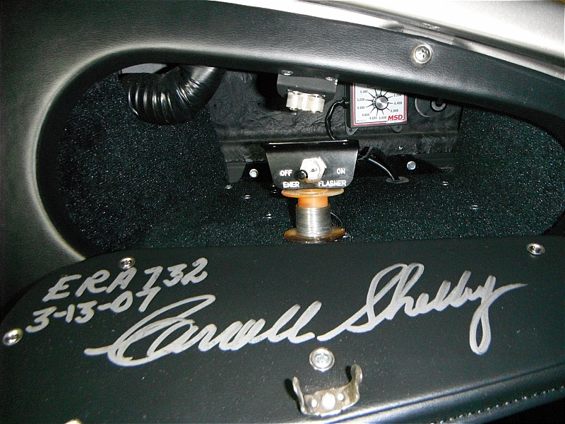
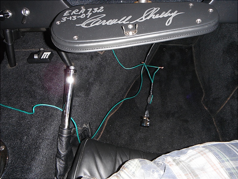
Wire your switch and run the wires out the back of the glove box, down to the passenger's feet area. (Note the cool adjustable rev limiter in the far back of my glove box.)
Test wire everything up. Put the fused flasher in line with the feed from the master circuit breaker, and run a temporary wire over to the five strands on the driver's side. Test it out! Then make sure your brake lights and turn signals work normally when the switch is turned off.
Assuming everything is working right, neaten it up and mount everything up under the dash. Zip tie your wires up and make sure everything is insulated properly.
Go back to your glove box and mount your switch. I was going to put it up on the top of the glove box, but instead decided to put it over on the right hand side.


 2Likes


 Threaded Mode

