Welcome to Club Cobra! The World's largest
non biased Shelby Cobra related site!
- » Representation from nearly all
Cobra/Daytona/GT40 manufacturers
- » Help from all over the world for your
questions
- » Build logs for you and all members
- » Blogs
- » Image Gallery
- » Many thousands of members and nearly 1
million posts!
YES! I want to register an account for free right now!
p.s.: For registered members this ad will NOT show
 
 Main Menu
|
|
Nevada Classics
|
|
Advertise at CC
|
|
December 2025
|
| S |
M |
T |
W |
T |
F |
S |
| |
1 |
2 |
3 |
4 |
5 |
6 |
| 7 |
8 |
9 |
10 |
11 |
12 |
13 |
| 14 |
15 |
16 |
17 |
18 |
19 |
20 |
| 21 |
22 |
23 |
24 |
25 |
26 |
27 |
| 28 |
29 |
30 |
31 |
|
|
|
|
|
CC Advertisers
|
|
 2Likes 2Likes

06-30-2007, 06:45 PM
|
 |
CC Member

|
|
|
Join Date: Mar 2001
Location: Provo,
Ut
Cobra Make, Engine: Kirkham, 427
Posts: 6,990
|
|

 Not Ranked
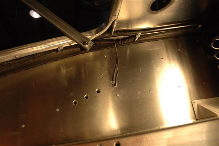
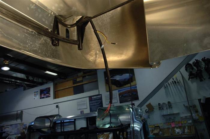
The rear wiring harness now travels along the edges of the trunk tubes.
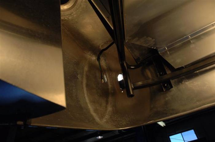
The left side wiring harness also has the wires that go to the trunk license plate light. There is both a power and a ground that goes to the trunk. Notice how the harness rivets to the under side of the tubes in the trunk. This is the SAME on both the left and the right side.
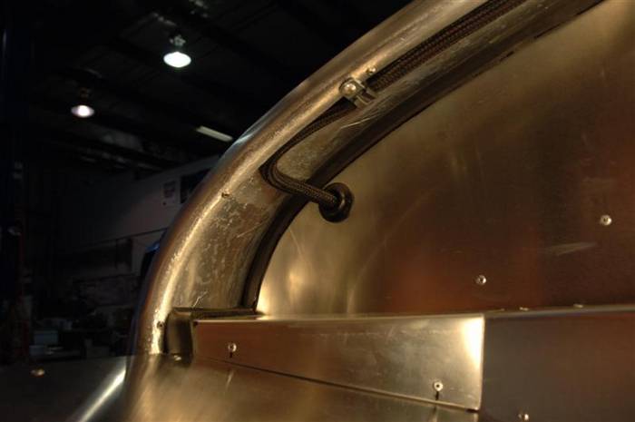
And then out through a hole in the aluminum side panels. REMEMBER THE GROMMET! This is a picture of the left side of the wiring harness. The left side has a BIGGER grommet than the right side as both the tail lights and the fuel tank sending unit wiring are in the same part of the harness here.
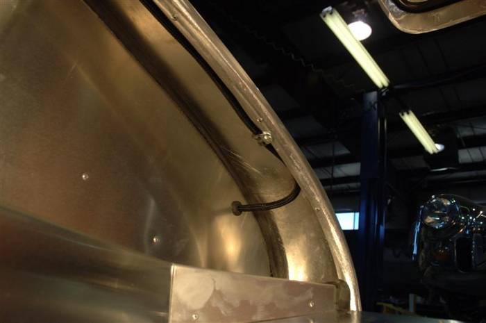
Here is a picture of how the right side harness runs and where it exits the panel to go to the tail lights. Original Cobras run the wiring the same way.
Last edited by David Kirkham; 07-24-2007 at 01:06 PM..
|
06-30-2007, 07:01 PM
|
|
CC Member
|
|
|
Join Date: Mar 2001
Location: Provo,
Ut
Cobra Make, Engine: Kirkham, 427
Posts: 6,990
|
|
Not Ranked
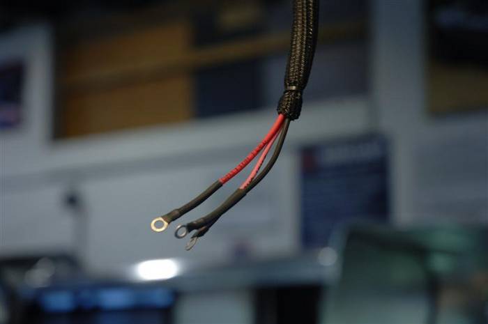
Here is a picture of the right rear tail light wires.
Here is a picture of the left rear tail light and fuel level sending unit wires.
Close up of the tail light wires.
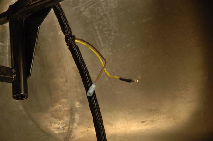
Close up of the fuel level sending unit wires.
Last edited by David Kirkham; 07-02-2007 at 01:53 PM..
|
06-30-2007, 07:06 PM
|
|
CC Member
|
|
|
Join Date: Mar 2001
Location: Provo,
Ut
Cobra Make, Engine: Kirkham, 427
Posts: 6,990
|
|
Not Ranked
place holder for fuel sender hook up
Last edited by David Kirkham; 07-03-2007 at 09:30 AM..
|
06-30-2007, 07:30 PM
|
|
CC Member
|
|
|
Join Date: Mar 2001
Location: Provo,
Ut
Cobra Make, Engine: Kirkham, 427
Posts: 6,990
|
|
Not Ranked
place holder for license plate light hook up
Last edited by David Kirkham; 07-03-2007 at 09:30 AM..
|
06-30-2007, 07:36 PM
|
|
CC Member
|
|
|
Join Date: Mar 2001
Location: Provo,
Ut
Cobra Make, Engine: Kirkham, 427
Posts: 6,990
|
|
Not Ranked

On the brake pedal box.
Here is a picture of the brake pedal box. In original Cobras the brake pedal box was not removable. Worse, the bottom of the pedal box was solid. The bottom didn't come off. It is VERY common for current owners of original cars to cut out the bottom of their pedal boxes so they can work on them. It is a most miserable chore to have to assemble a pedal box from inside the cockpit when the steering wheel is hitting you in the back and the gear shift lever is stuck in places I would rather not remember. Next time I have to install a pedal box in an original car I will hire someone from Cirque du Soleil to do it for me.
Anyway, here is what the bottom of our box looks like. It looks just like an original one, except we can unbolt ours and we rivet an aluminum access cover on the bottom of ours.

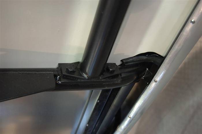
This is where we bolt the pedal box onto the car. There are two bolts in the rear (shown in the picture) and two bolts in the front. (not shown...at least yet).
Also, I had to take this picture from another one of our cars (Bobby Rahal's car  ) because my guys are bolting parts on faster than I can type!
Last edited by David Kirkham; 07-03-2007 at 09:44 AM..
|
06-30-2007, 07:43 PM
|
|
CC Member
|
|
|
Join Date: Mar 2001
Location: Provo,
Ut
Cobra Make, Engine: Kirkham, 427
Posts: 6,990
|
|
Not Ranked
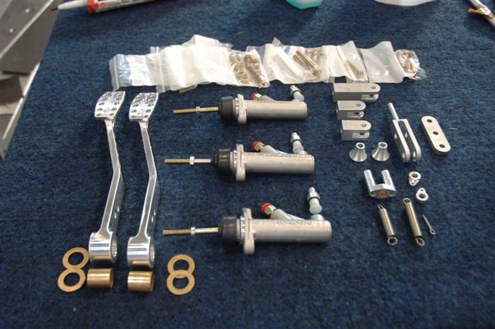
Here are all the pieces you will need to complete your pedal box.
Here are your bolts.
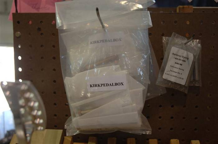
Here are your parts. We call them the pedal box guts.
If you look closely at the brake and clutch pedal arms, you can see we drilled two holes in them. That way both pedals can be used for either the brake or the clutch arm. The upper hole (the one towards the part you push on with your foot) is used to hook to the clutch master cylinder. The lower hole is used to hook to the brake master cylinders balance bar assembly.
Last edited by David Kirkham; 07-03-2007 at 09:49 AM..
|
06-30-2007, 08:09 PM
|
|
CC Member
|
|
|
Join Date: Mar 2001
Location: Provo,
Ut
Cobra Make, Engine: Kirkham, 427
Posts: 6,990
|
|
Not Ranked
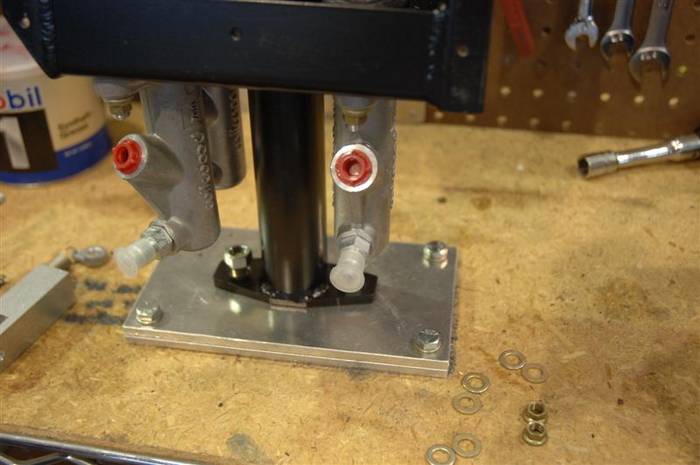
In this picture you can see 3 master cylinders. The one on the left (in the picture) is for the clutch. The one closest to you on the right (in the picture) is the FRONT brake master cylinder. The one furthest away from you on the right (in the picture) is the rear master cylinder. If you read the size on the master cylinder for the front brake master cylinder you can see it reads .700 or 11/16" bore.
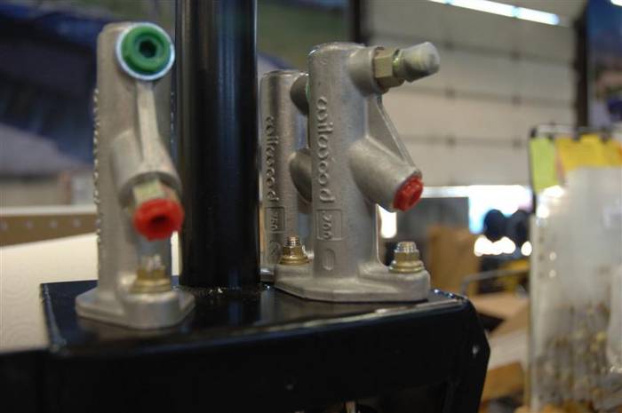
Rear brake master cylinder is .750 or 3/4" bore.

The clutch master cylinder is .700 or 11/16"--just like the front brake master cylinder.
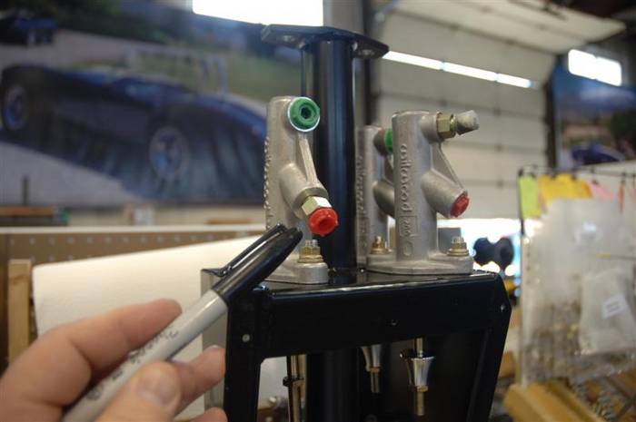
You can see in the below picture a little fitting that comes on all of the Wilwood master cylinders--straight out of the box. (I am pointing to it in the above picture). We throw them straight in the trash. You won't need them. Also, Joe got a little bit ahead of me assembling this pedal box and you can see the front brake master cylinder already has the brake reservoir fitting in it. On the master cylinder, the front opening (the one furthest away from the push rod) is a #4 o-ring boss fitting. The other side of the fitting is a #4 JIC which connects to the brake reservoir cans. There is no pressure on this fitting. It is simply where the brake fluid enters the master cylinder from the brake reservoir cans. If you get the billet reservoir can option on our list, then your brake fluid will not be rusty when it enters here.
Last edited by David Kirkham; 07-02-2007 at 01:39 PM..
|
06-30-2007, 08:12 PM
|
|
CC Member
|
|
|
Join Date: Mar 2001
Location: Provo,
Ut
Cobra Make, Engine: Kirkham, 427
Posts: 6,990
|
|
Not Ranked
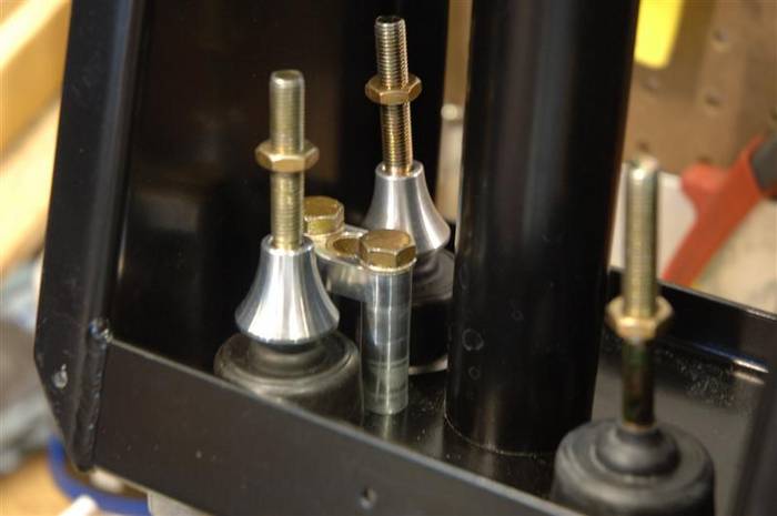
After you get your master cylinders bolted in, you will want to put you "bell stops" on your brake master cylinders. The bell stops are a fail safe device. They are there in case of failure of one master cylinders. If one of the master cylinders fails, then it will no longer offer pressure against the balance bar and all of the brake pedal travel will then go to the failed master cylinder. This is a good way to meet your Maker very unexpectedly--or at least to ruin the leather in your seat. Under failed master cylinder conditions, the bell stop only lets the failed master cylinder push rod engage so far before it stops (hence the name) and forces the balance bar to act on the other cylinder. Don't forget them or someone on this forum (probably Jamo) will nominate you for the Darwin awards.
In between the master cylinders you can see the "brake guide." There is a long pin on the balance bar fork that goes into this bushing. The guide pin keeps the brakes aligned so they work properly. If you forget to put this piece in the brakes will jam and Jamo will be posting about you.
Last edited by David Kirkham; 07-03-2007 at 09:56 AM..
|
06-30-2007, 08:33 PM
|
|
CC Member
|
|
|
Join Date: Mar 2001
Location: Provo,
Ut
Cobra Make, Engine: Kirkham, 427
Posts: 6,990
|
|
Not Ranked
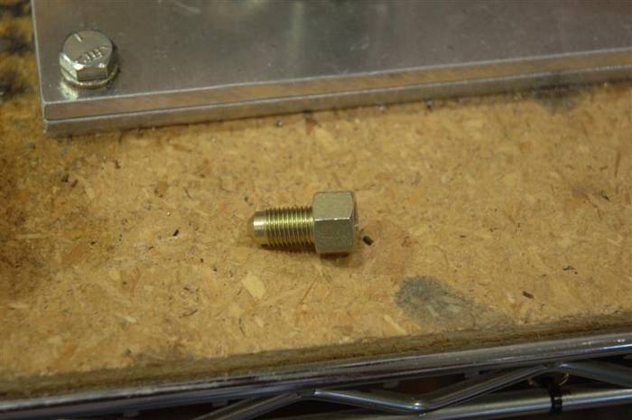
Here the #4 o-ring boss to #4 JIC adapters are fitted into the master cylinders. You have to be VERY careful when you install them to not cut the o-rings or they WILL leak!
Last edited by David Kirkham; 07-02-2007 at 12:47 PM..
|
| Thread Tools |
|
|
| Display Modes |
 Hybrid Mode Hybrid Mode
|
 Posting Rules
|
You may not post new threads
You may not post replies
You may not post attachments
You may not edit your posts
HTML code is Off
|
|
|
All times are GMT -7. The time now is 04:54 AM.
|
|


