Main Menu
|
|
Nevada Classics
|
|
Advertise at CC
|
| S |
M |
T |
W |
T |
F |
S |
| |
|
|
|
|
1 |
2 |
| 3 |
4 |
5 |
6 |
7 |
8 |
9 |
| 10 |
11 |
12 |
13 |
14 |
15 |
16 |
| 17 |
18 |
19 |
20 |
21 |
22 |
23 |
| 24 |
25 |
26 |
27 |
28 |
29 |
30 |
| 31 |
|
|
|
|
|
|
|
|
CC Advertisers
|
|
 2Likes 2Likes

01-29-2012, 10:21 PM
|
|
CC Member

|
|
|
Join Date: Mar 2009
Location: Mendota,
IL
Cobra Make, Engine:
Posts: 697
|
|

 Not Ranked
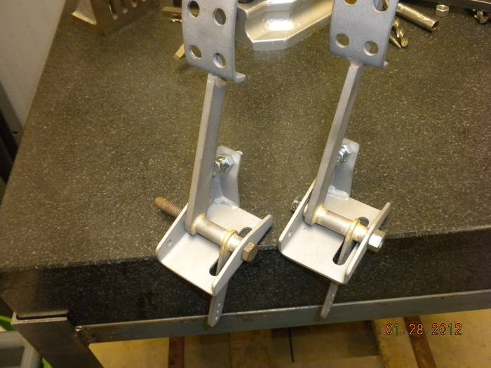
 Gas pedal mounting bracket
Today I built some mounting brackets for the gas pedal. These are bolted to the side of the pedal box.
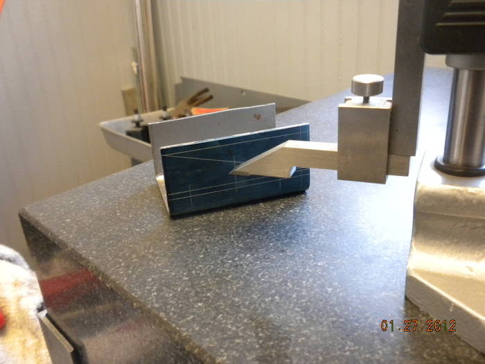
The proccess I used to build them was. First I cut a blank to the width It needs to be but I left it longer than needed. Next I took a piece of scrap of the same thickness and scribed lines where the bends should be and bent in the order that the real bracket will be bent. I then measured the piece, in this case the lines were scribed at 2 inches, the actual measurement of the part was 1.900. Now I know I need to add .100 to my measurement. Now I scribe my lines at 2.100 on my part and bend, using this method you can usually have a part that measures within a few thousands of what you want it to be. By the way, I am bending this in a Di Acro 24in box and pan brake rated at 16 gauge. Bending 11gauge is called abusing it.
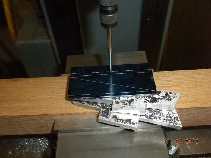
Next, I put layout bluing on the part and used a digital height gauge and layed out where the holes are to be drilled and the part needs to be trimmed.
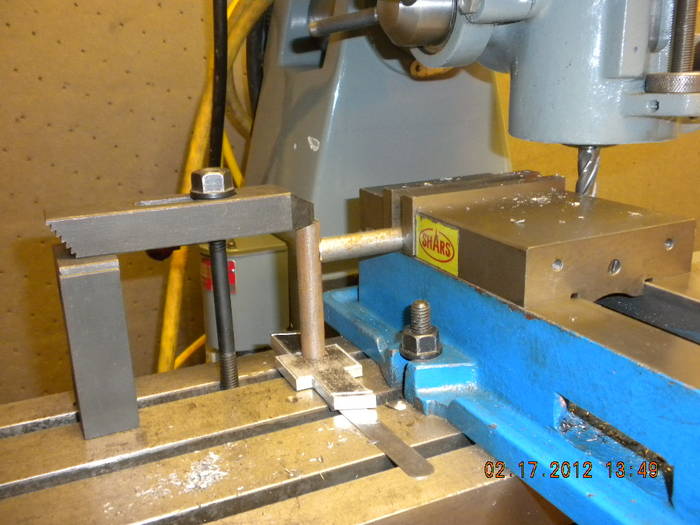
Next I clamped it in the mill and use a wiggle indicator to dial in where the holes need to be drilled.
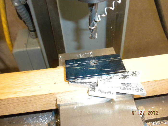
Part is center drilled and then drilled to size and then repeated for the other holes.
For the rest of the process I didn't take any pictures. The part was cut on all cut lines with a delta 4x6 band saw. A little file work to clean up sharp edges and you end up with a nice part. Using the same process make and bend the throttle stop bracket and weld it to the other part, throw in the bead blaster and clean it up. It is then ready for paint. I will post some more when I get a chance. Mark

|
01-29-2012, 09:48 PM
|
|
Senior Club Cobra Member
|
|
|
Join Date: Feb 2008
Location: Jacksonville,
FL
Cobra Make, Engine: VSE alum. frame, FFR carbonfiber body (under construction)
Posts: 293
|
|
Not Ranked
Keep building up the weld......then grind it down nice and smooth! Works for me (as long as you're getting good penetration).
|
01-30-2012, 03:15 AM
|
 |
Senior Club Cobra Member
|
|
|
Join Date: Sep 2000
Location: Holderness, NH, US of A,
NH
Cobra Make, Engine: CSX 4772 old iron FE
Posts: 5,499
|
|
Not Ranked
I saw those control arms. They may have been made in England, from original parts by the original guy in the original factory but they were originally welded together not brazed on suspension. There is a pretty good formula for calculating stock gain on bends based on angle, thickness, bend radii etc. Try using a material thickness for a 90 and see how close that is. The way we explain machinery abuse is it can bend 4 ft of 16 ga so it can bend 2 ft of 11 ga, same thing only different ha ha yeah right ;-)
Good work and progress.
|
01-31-2012, 01:02 PM
|
 |
CC Member
|
|
|
Join Date: Dec 2010
Location: Allen,
TX
Cobra Make, Engine: Werk77 289FIA
Posts: 1,296
|
|
Not Ranked
Quote:
Originally Posted by mickmate

The way we explain machinery abuse is it can bend 4 ft of 16 ga so it can bend 2 ft of 11 ga, same thing only different ha ha yeah right ;-)
Good work and progress.
|
The difference is, you need 1.9 t/ft (16Ga) or 9.2 t/ft (11Ga) - with a 0.875 V.
The 50% does not quite cut it hehe

__________________
Scratch build 289 FIA see the Scratch builder forum on CC - sold
DRB GT40 MK1 red #49- sold
FF5 Mk4 #7733 302/T5/IRS - dark blue - sold
FF5 MK4 #7812 427/TKO/IRS - Guardsman Blue - sold
FF5 MK4 #8414 501/TKO600/48IDA Ollie the Dragon #91 - sold
FF5 Daytona Coupe 347/TKO/IRS Homage CSX2299 Viking Blue - sold
SPF 2063
|
01-31-2012, 08:13 PM
|
 |
CC Member
|
|
|
Join Date: Mar 2003
Location: McConnellsburg,
PA
Cobra Make, Engine: ERA FIA #2124
Posts: 687
|
|
Not Ranked
Looking forward to more progress!
- Allen.
|
02-02-2012, 10:53 AM
|
|
CC Member
|
|
|
Join Date: Mar 2009
Location: Mendota,
IL
Cobra Make, Engine:
Posts: 697
|
|
Not Ranked
Brake abuse
Quote:
The difference is, you need 1.9 t/ft (16Ga) or 9.2 t/ft (11Ga) - with a 0.875 V.
The 50% does not quite cut it hehe
|
Had to think about this ..... didn't know what it meant. When the lightbulb came on press brake! Looking at your build and looking at the background in some of the pictures you know a lot about them.
I thought about making a small one for a hydraulic shop press. But I don't have one of those either. A friend has one I can use. Anyhow I have been using my 24 inch diacro box and pan brake. It is only rated at 16 gage. Doing a piece of full width (24 in) 16 gauge and to get a nice crisp bend is tough on this machine. The brake has some spring to it. When I try to bend 11 gauge in narrower widths is doable but hard to get a nice tight radius. When I use it to bend 11 gauge I loose material in the bend, not gain. My scribed bend line ends up part way up in the radius. That is why I was saying that if you draw 2 lines at 2 in apart and make the bend I end up with the sides being 1.900 apart. That's why I bend a practice piece so I know how much to fudge my numbers.
Pic of my brake

|
02-02-2012, 11:24 AM
|
|
CC Member
|
|
|
Join Date: Mar 2009
Location: Mendota,
IL
Cobra Make, Engine:
Posts: 697
|
|
Not Ranked
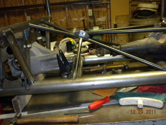
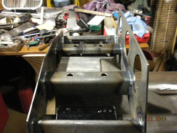
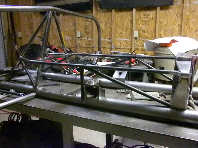
Chassis
Well Tuesday was a nice warm day(60 deg) . I spent most of the day in the unheated garage. Here's a shot of my progress when I went in the house at midnight.
 ,
If anyone has any questions or need a different view, just ask.
Krausewich,
Don't worry about asking things out of sequence. I am not doing anything in sequence here. I am just building as I go. If I get stumped on one thing I move on to something else, work on the frame, work on the buck, make new brackets. At the time I asked the question about making the rain gutters, I didn't even know what a pullmax or a tipping wheel was. This build will be jumping around a lot. When I find the pictures of how I built the rain gutters, I will get them posted. Thanks Mark |
02-02-2012, 03:09 PM
|
|
CC Member
|
|
|
Join Date: Mar 2009
Location: Mendota,
IL
Cobra Make, Engine:
Posts: 697
|
|
Not Ranked
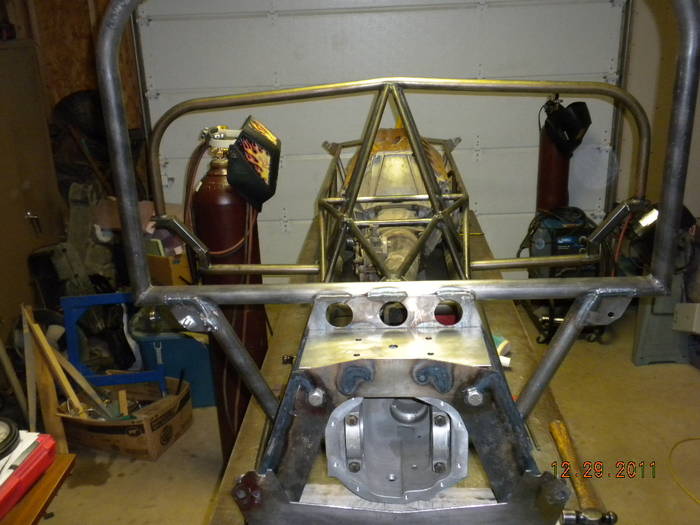
Chassis details
This is a early frame build picture. It is now the one under my buck
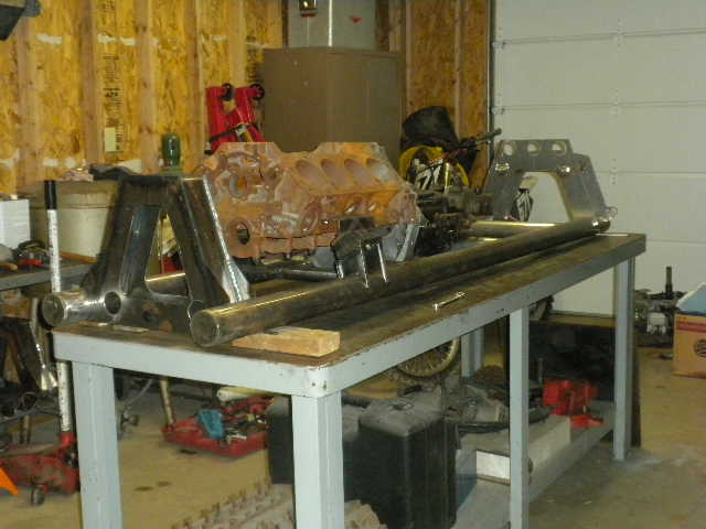
Front backbone detail
More backbone detail

Closer look at backbone

Better look at removable bockbone

Last edited by MAStuart; 02-02-2012 at 03:16 PM..
Reason: pics did not show up
|
02-02-2012, 03:58 PM
|
|
CC Member
|
|
|
Join Date: Mar 2009
Location: Mendota,
IL
Cobra Make, Engine:
Posts: 697
|
|
Not Ranked
More pictures
|
02-08-2012, 08:49 PM
|
|
CC Member
|
|
|
Join Date: Feb 2003
Location: Plymouth,
MA
Cobra Make, Engine: MidStates, 351C, 4spd, 9"
Posts: 405
|
|
Not Ranked
Killer home built brackets !!! You really make some nice stuff.
Eagerly awaiting the progress.
Mike.
__________________
"It's not about getting from point A to point B. It is the point"
-J. James
M. Krause
1.508.944.3368
|
02-11-2012, 11:50 PM
|
|
CC Member
|
|
|
Join Date: Jul 2003
Cobra Make, Engine: Unique Motorcars 289 USRRC, 1964 289 stroked to 331, toploader
Posts: 1,143
|
|
Not Ranked
Awesome work! We appreciate you sharing  ... keep the photos coming.
__________________
Paul
Unique Motorcars 289 USRRC
1964 289 5-bolt block
Toploader and 3.31 rear
|
02-25-2012, 04:19 PM
|
|
CC Member
|
|
|
Join Date: Mar 2009
Location: Mendota,
IL
Cobra Make, Engine:
Posts: 697
|
|
Not Ranked
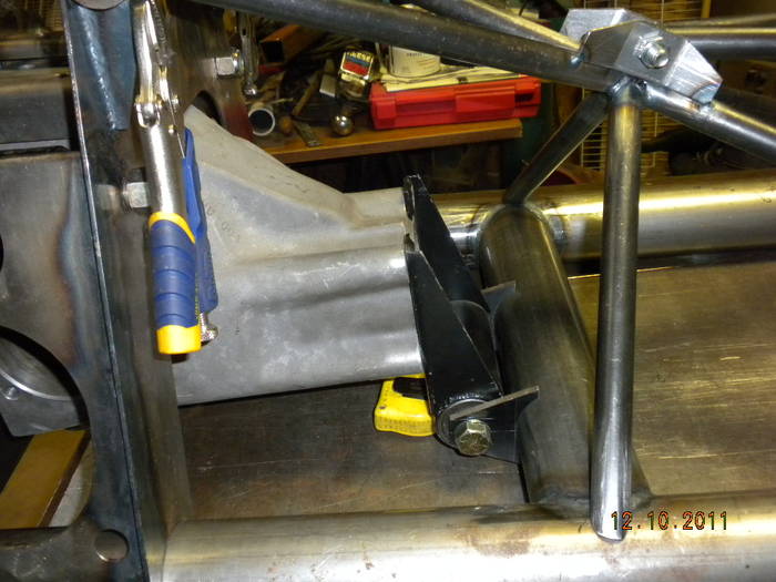
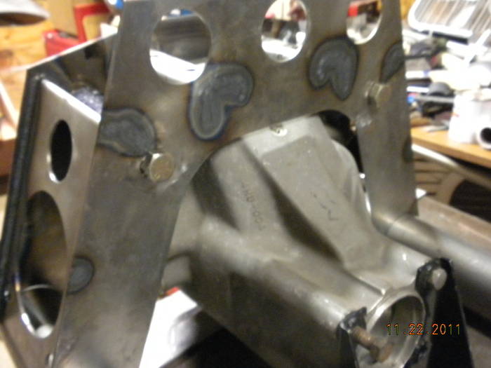
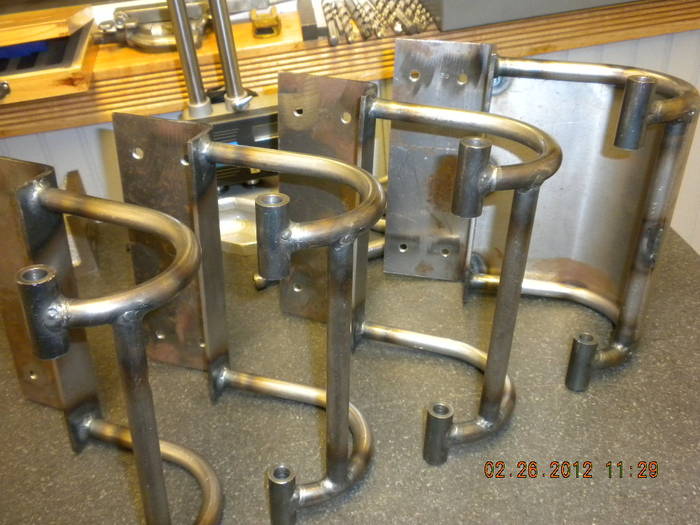
Question about daytona coupe door hinges?
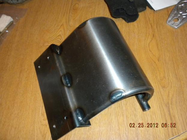
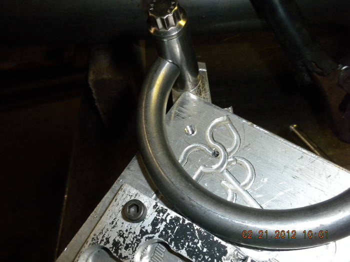
I have been busy building door hinges for my coupe. They are build according to specs of the plans. The plans don't specifiy anything about welding. I have spent alot of time looking on club cobra and elsewhere on the internet trying to find detailed pictures of the original daytona coupe hinges. My question is, how were they welded, not the process but how were they welded as far as the curved plate. Were they welded completely around it or did they skip around similar to what I have shown in the picture?
Thanks in advance. Later I will try to post some pictures of the process I went thru to build these hinges. Mark
|
02-28-2012, 11:34 PM
|
|
CC Member
|
|
|
Join Date: Mar 2009
Location: Mendota,
IL
Cobra Make, Engine:
Posts: 697
|
|
Not Ranked
Building hinges
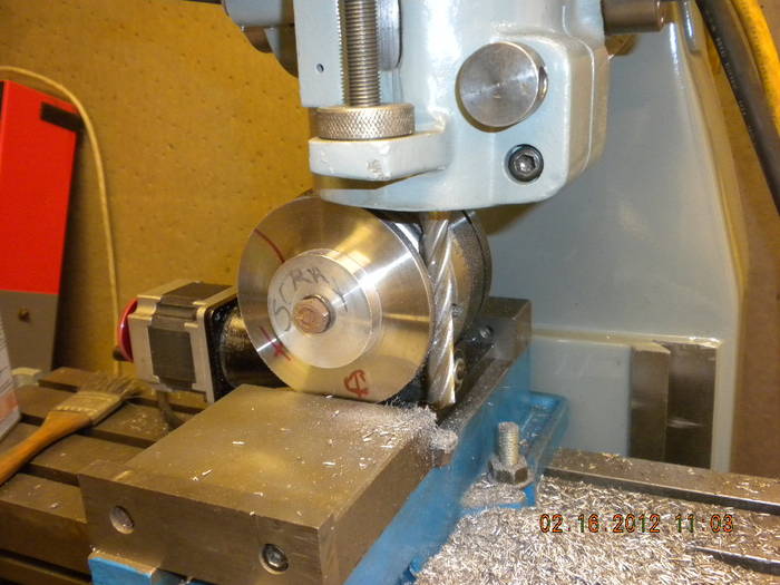
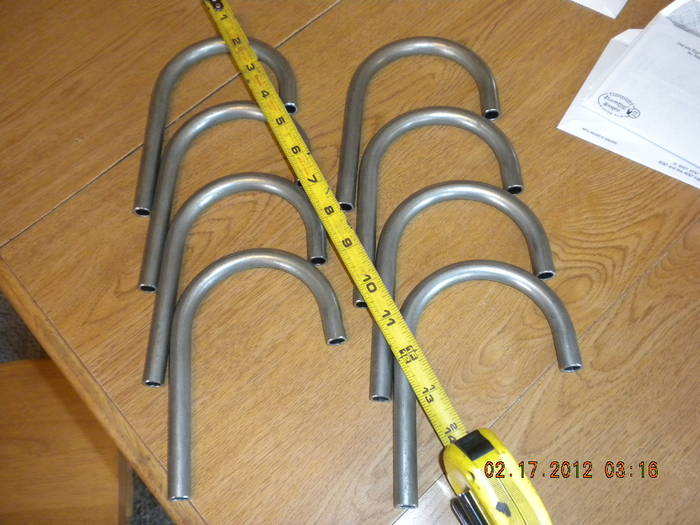
To make the hinge I needed to bend some 1/2 inch tubing. I wanted them to be all the same. I have a diacro hand bender but no 1/2 inch die with 3 1/2 center radius. I turned a blank on the lathe and finished it in the mill on a rotary table I also made a follow bar.
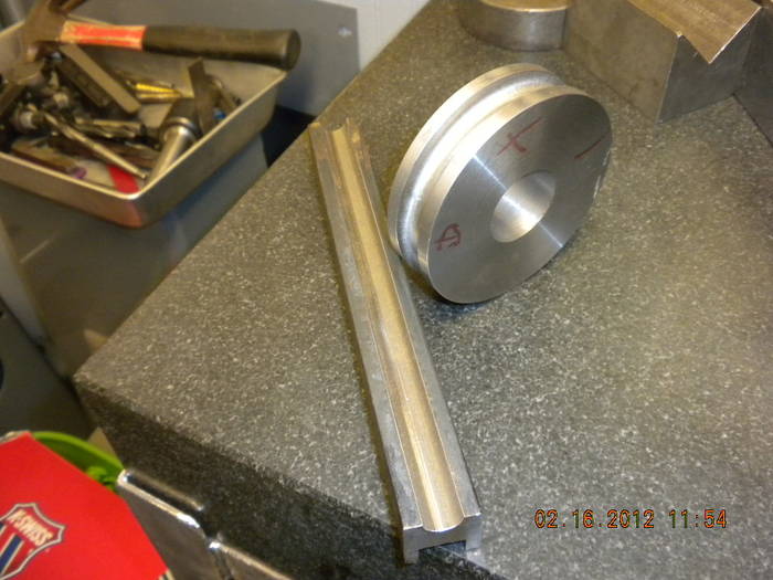
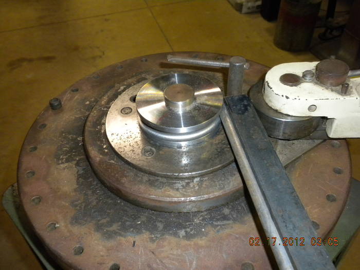
Here they are with a tube blank mounted on the bender
Tubing blanks all bent and they all came out nice
Next Imade a jig from scrap to cut them all to the same length
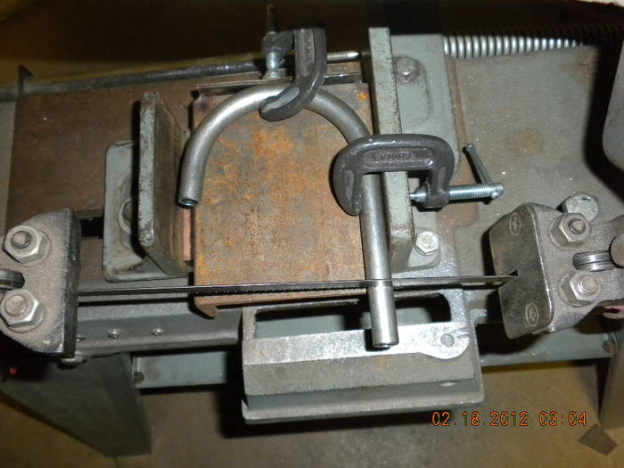
The same jig in the mill to cope the other end
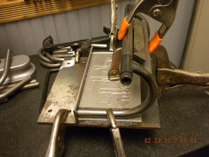
Another jig made from scrap to hold the end tube for welding
Here it is all ready to weld.

Thats all for now .......... Mark |
03-01-2012, 03:55 PM
|
|
CC Member
|
|
|
Join Date: Mar 2009
Location: Mendota,
IL
Cobra Make, Engine:
Posts: 697
|
|
Not Ranked
Today's installment
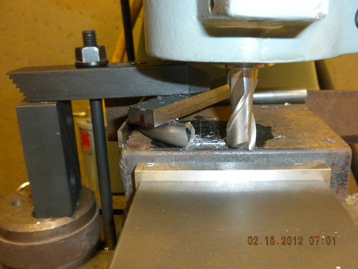
After all the pivot tubes welding was done I needed to cope the cross tubes .I put them in the mill vice and milled one end on each tube. I then clamped a stop to the table. Now it is easy to cope the other end to the right length and have the copes line up.
Now it is time to clamp all the parts together. Back to the scrap box and some vicegrips and I came up with this.
After welding
I then sheared some 18 gage to size and ran them thru my slip roller . Here they are after welding to the hinge.
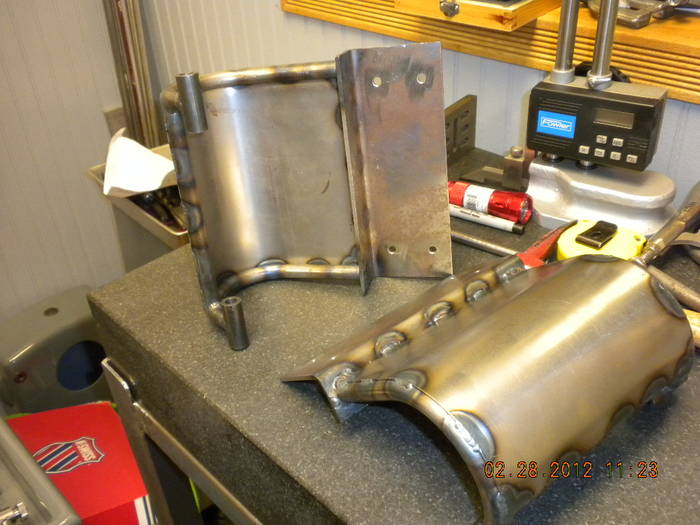
I still need to know if these were welded like this or should they have a weld all the way around. Thats all for now. Mark |
03-01-2012, 06:21 PM
|
 |
CC Member
|
|
|
Join Date: May 2003
Location: Bugtussell,
AR
Cobra Make, Engine: FFR 4859GT Spyder GT 414W EFI
Posts: 257
|
|
Not Ranked
Howdy,
OMG! Your skills are unbelievable!
Was far as the welding goes I would ask Chuck. If anyone would know it would be him. If in doubt leave them the way they are, they look great!
Keep the pics and updates coming!
Paul
__________________
"A veteran - whether active duty, retired, national guard, or reserve - is someone who, at one point in his or her life, wrote a blank check made payable to The 'United States of America', for an amount of 'up to and including my life.'" (Author unknown)
|
03-02-2012, 03:08 AM
|
|
CC Member
|
|
|
Join Date: Mar 2006
Cobra Make, Engine:
Posts: 231
|
|
Not Ranked
A very very professional work with professional equipment.
Keep us posted.
Cheers
Migge
|
03-02-2012, 03:21 AM
|
 |
CC Member
|
|
|
Join Date: Nov 2001
Location: Windham,,
Me
Cobra Make, Engine:
Posts: 1,590
|
|
Not Ranked
Think of the investment in machines,tools and equipment just to start a scratch build like this.Certainly way beyond the means of most.Then there has to be the creative mentality to pull the build off.Enjoy seeing the progress,ground up built my car (from a kit) and can relate to the parts and pieces which in itself is very interesting.Looking forward to the next installment.Mike
|
03-29-2012, 03:54 PM
|
|
CC Member
|
|
|
Join Date: Mar 2009
Location: Mendota,
IL
Cobra Make, Engine:
Posts: 697
|
|
Not Ranked
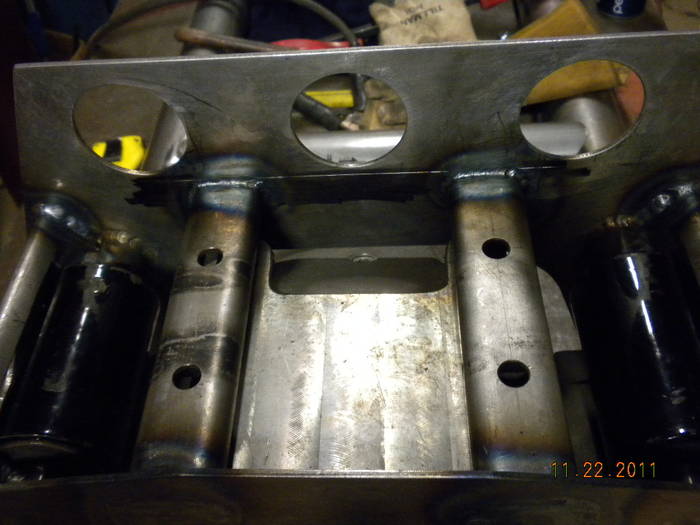
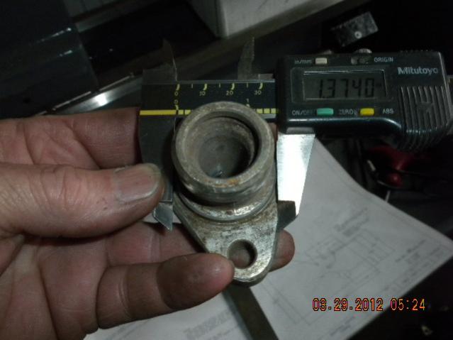
Pedal box holes
Hey ! I'm back to work on my pedal box and my plans call for 1 1/2 inch holes for the master cylinders and 5/16 bolt holes with 2 1/4 spacing. But I have a girling and the bolt spacing is the same and the center hole only needs to be 1 3/8 . Willwoods are the same . Does the large hole need to be 1 1/2 to clear the master cyl with the rubber boot on.
|
03-29-2012, 05:09 PM
|
 |
CC Member
|
|
|
Join Date: Apr 2006
Location: Charlottesville,
va
Cobra Make, Engine: Coombe, Shelby Block 496
Posts: 1,187
|
|
Not Ranked
Yes, 1.5 inches
|
04-03-2012, 04:24 AM
|
 |
CC Member
|
|
|
Join Date: Feb 2009
Location: Near Huntsville, Al,
AL
Cobra Make, Engine:
Posts: 38
|
|
Not Ranked
Thanks for showing your hinges Mark. I'm redoing the decklid on my roadster and your photos made the light bulb come on.
I've wished a jillion times I had gone with a superleggera approach.
__________________
Kerry Pinkerton
|
| Thread Tools |
|
|
| Display Modes |
Rate This Thread |
 Hybrid Mode Hybrid Mode
|
|
 Posting Rules
|
You may not post new threads
You may not post replies
You may not post attachments
You may not edit your posts
HTML code is Off
|
|
|
All times are GMT -7. The time now is 10:22 AM.
Links monetized by VigLink
|