Welcome to Club Cobra! The World's largest
non biased Shelby Cobra related site!
- » Representation from nearly all
Cobra/Daytona/GT40 manufacturers
- » Help from all over the world for your
questions
- » Build logs for you and all members
- » Blogs
- » Image Gallery
- » Many thousands of members and nearly 1
million posts!
YES! I want to register an account for free right now!
p.s.: For registered members this ad will NOT show
 
 Main Menu
|
|
Nevada Classics
|
|
Advertise at CC
|
|
April 2026
|
| S |
M |
T |
W |
T |
F |
S |
| |
|
|
1 |
2 |
3 |
4 |
| 5 |
6 |
7 |
8 |
9 |
10 |
11 |
| 12 |
13 |
14 |
15 |
16 |
17 |
18 |
| 19 |
20 |
21 |
22 |
23 |
24 |
25 |
| 26 |
27 |
28 |
29 |
30 |
|
|
|
|
CC Advertisers
|
|

05-06-2013, 08:44 PM
|
 |
CC Member

|
|
|
Join Date: Jul 2011
Location: Sydney,
NSW
Cobra Make, Engine: Puckett 250 GTO - LS1
Posts: 567
|
|

 Not Ranked
 Holden ABS info required - Thanks
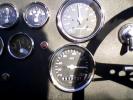
I'm trying to use as many parts from the one donor car (VZ Ute) as possible and that includes the brake booster and m/c. I have them mounted but as I start to make the hard lines I'm unsure which ports on the m/c are which. I took photos as I pulled the donor apart but I don't have one of the top of the ABS unit which, if I recall correctly, was stamped 'front' and 'rear'.
Can someone with access to a late model Holden with ABS look to see if the ports marked #1 and #2 in the photo have 'front' and 'rear' stamped near them, and, which ports on the m/c the lines are connected to. Thanks.
|
-
Advertising

05-07-2013, 10:51 PM
|
|
CC Member
|
|
|
Join Date: Jul 2011
Location: Sydney,
NSW
Cobra Make, Engine: Puckett 250 GTO - LS1
Posts: 567
|
|
Not Ranked
I spent this morning wandering around the car sale yards having a look. It seems you have to be VERY model specific with the m/c and ABS. I think I have it sorted out but if the car swaps ends the first time I jump on the brakes then I just switch the lines to the other port!
Last edited by PeterAllen; 05-08-2013 at 04:42 AM..
|
05-08-2013, 03:50 AM
|
 |
CC Member
|
|
|
Join Date: Jan 2007
Location: Melbourne,
VIC
Cobra Make, Engine: Harrison, 6.0L Chev
Posts: 2,513
|
|
Not Ranked
Peter, I'd be dropping into the local Holden dealer asking to have a look at their workshop manuals online. I had some luck at Nissan last year trying to identify the part numbers for rear diff splines - asked a few questions and they pulled up an exploded diagram of the diff with all the part numbers and printed out a few pages for me. Might be worth a try?
Make up a story about a minor accident severing a brake line or something like that. Just don't ask for favours on a Saturday morning. 
__________________
"A spectacularly fast car in a grand if dated tradition."
|
05-08-2013, 04:24 AM
|
 |
CC Member
|
|
|
Join Date: Oct 2008
Location: Perth,
WA
Cobra Make, Engine: G-Force Mk1, LS1, T56, Jag S3 suspension
Posts: 587
|
|
Not Ranked
Mine is a VY but looks similar.

The #1 in your photo is labeled RR and #2 is labeled RF.
The fat pipe (#1/RR) runs to the front of the MC with the smaller pipe (#2/RF) running to the rear, same as you have yours setup.
Hope that helps!
--JC |
05-08-2013, 04:30 AM
|
|
CC Member
|
|
|
Join Date: Jul 2011
Location: Sydney,
NSW
Cobra Make, Engine: Puckett 250 GTO - LS1
Posts: 567
|
|
Not Ranked
That’s not a bad idea 'sambo' and it might show if one port is pushing more fluid than another, or if there are pressure equalising bore holes, etc, but I would like a written or verbal explanation of the functionality of the m/c. I believe (but I’m not certain) that the proportioning on a Ute takes place at the rear where a sensor distributes the brake bias according to the load being carried. I’m hoping that means the m/c puts out equal pressure through both ports and the stand-alone proportioning valve (Wilwood) I’m fitting can be adjusted to the correct bias - via some trial and error.
Probably the only person who knows is a Holden engineer who worked on the design but who is now living off a redundancy package! Remember the good old days when a mechanic knew something about cars and did more than ‘remove and replace’.
Last edited by PeterAllen; 05-08-2013 at 04:40 AM..
|
05-08-2013, 04:39 AM
|
|
CC Member
|
|
|
Join Date: Jul 2011
Location: Sydney,
NSW
Cobra Make, Engine: Puckett 250 GTO - LS1
Posts: 567
|
|
Not Ranked
JC - I think the RR and RF refer to the ports on the side of the ABS.
Can you tell me what the other stamping are? One seems to start with 'M' suggesting m/c. Also, can you confirm that the 'fat' one runs to the port on the m/c which is furthest from the booster? Thanks.
|
05-08-2013, 05:04 AM
|
|
CC Member
|
|
|
Join Date: Oct 2008
Location: Perth,
WA
Cobra Make, Engine: G-Force Mk1, LS1, T56, Jag S3 suspension
Posts: 587
|
|
Not Ranked
Yes, there are more now that I've checked again...


and the fat pipe (#1, MC2) goes to the furthest from the booster, closest to the ABS unit. Not sure why it's upside down... |
05-08-2013, 05:36 AM
|
|
CC Member
|
|
|
Join Date: Jul 2011
Location: Sydney,
NSW
Cobra Make, Engine: Puckett 250 GTO - LS1
Posts: 567
|
|
Not Ranked
I believe I have once again demonstrated my skill at making the simple rather difficult. It appears that most master cylinders have P and S cast on them which represent the Primary and Secondary outputs with the P closest to the booster as it is activated by the pushrod, whereas the secondary piston is operated by the primary piston, i.e. there is some delay.
The internet information suggest that rear drum cars have the rears connected to the primaries as they take more fluid to operate but on 4 disc cars the front receive fluid from the primary port. Using the ABS piping information I had come up with the fronts operating off the P outlet so Im reasonably confident Im on the right path.
|
05-08-2013, 04:34 PM
|
 |
CC Member
|
|
|
Join Date: Feb 2002
Location: Alice Springs, central Australia,
NT
Cobra Make, Engine: Classic revival kit (CR3181), gen III engine, T56 6 speed box, AU XR8 lsd diff
Posts: 5,699
|
|
Not Ranked
I dont have anything with me but common sence would say that the thicker pipe (MC2) be the front brakes (needs to push more fluid than the rears) so MC1 would be the rears.
The the other markings read
RR = Right rear,
LR= Left Rear
RF= Right Front
LF= Left Front
__________________
Cruising in 5th

---------------------------------------------
Never be afraid to do something new, Remember, Amateurs built the Ark: Professionals built the Titanic.
|
05-08-2013, 05:39 PM
|
|
CC Member
|
|
|
Join Date: Jul 2011
Location: Sydney,
NSW
Cobra Make, Engine: Puckett 250 GTO - LS1
Posts: 567
|
|
Not Ranked
But why is the thicker inlet pipe closer to the RR & RL outlets? Just to add to the confusion, my donor car used the thicker pipe for both lines from the m/c to the ABS.
|
05-08-2013, 09:54 PM
|
|
CC Member
|
|
|
Join Date: Feb 2002
Location: Alice Springs, central Australia,
NT
Cobra Make, Engine: Classic revival kit (CR3181), gen III engine, T56 6 speed box, AU XR8 lsd diff
Posts: 5,699
|
|
Not Ranked
Good question, one for which I am afraid I do not have an answer.
__________________
Cruising in 5th
---------------------------------------------
Never be afraid to do something new, Remember, Amateurs built the Ark: Professionals built the Titanic.
|
05-08-2013, 10:28 PM
|
|
CC Member
|
|
|
Join Date: Jan 2007
Location: Melbourne,
VIC
Cobra Make, Engine: Harrison, 6.0L Chev
Posts: 2,513
|
|
Not Ranked
I think you'll find that the narrower tube to the front results in higher fluid velocity (same amount of fluid through a smaller hole), resulting in more force to the front - all things being equal such as caliper piston size, brake pad/disc surface area, etc.
Edit: I'm 100% certain I may be incorrect about this.
__________________
"A spectacularly fast car in a grand if dated tradition."
Last edited by sambo; 05-08-2013 at 10:31 PM..
|
05-08-2013, 11:06 PM
|
 |
CC Member
|
|
|
Join Date: Jan 2001
Location: Sunbury,
VIC
Cobra Make, Engine: Rat Rod Racer, LS1 & T56
Posts: 5,391
|
|
Not Ranked
Higher fluid velocity diesn't mean more force. I'm more inclined to think that since the front calipers are 2 or 4 piston they will require more flow than the rear single piston calipers hence the larger diameter pipe. More piston surface area means more flow required.
That being said a lot of MCs have the front circuit closest to the fire wall. There is often a spring and proportioning valve between the pistons in the MC. The front circuit is acuated first and then a spring transmits the force to the next piston in line that feeds the rear. If that were the case then your MC has the fat pipe to the rear circuit.
The rear circuit is also further away and the longer a pipe is the less it will flow. Something to do with drag against the internal walls of the pipe. So a larger pipe feed int the rear would compensate for the reduced flow of the longer line.
They may have also used different sizes s the nuff nuff tech in the service department doesn't geth them mixed up 
Cheers
__________________
Mike Murphy
Melbourne Australia
Last edited by Aussie Mike; 05-08-2013 at 11:17 PM..
|
05-08-2013, 11:55 PM
|
|
CC Member
|
|
|
Join Date: Jan 2007
Location: Melbourne,
VIC
Cobra Make, Engine: Harrison, 6.0L Chev
Posts: 2,513
|
|
Not Ranked
So if the fluid is travelling faster to the front, wouldn't it result in greater piston travel and therefore more braking force (all other things being equal)?
__________________
"A spectacularly fast car in a grand if dated tradition."
|
05-09-2013, 12:17 AM
|
|
CC Member
|
|
|
Join Date: Feb 2002
Location: Alice Springs, central Australia,
NT
Cobra Make, Engine: Classic revival kit (CR3181), gen III engine, T56 6 speed box, AU XR8 lsd diff
Posts: 5,699
|
|
Not Ranked
But with a larger piston, it requires more fluid to shift it the same distance. Hence the requirement for more fluid.
__________________
Cruising in 5th
---------------------------------------------
Never be afraid to do something new, Remember, Amateurs built the Ark: Professionals built the Titanic.
|
05-09-2013, 12:28 AM
|
|
CC Member
|
|
|
Join Date: Jan 2007
Location: Melbourne,
VIC
Cobra Make, Engine: Harrison, 6.0L Chev
Posts: 2,513
|
|
Not Ranked
Gotchya!
__________________
"A spectacularly fast car in a grand if dated tradition."
|
05-09-2013, 03:44 AM
|
 |
CC Member
|
|
|
Join Date: Nov 2009
Location: Cheltenham,
Vic
Cobra Make, Engine: Classic Revival CR3516, LS3, Aussie Mike'd T-56, 3.70 LSD, AP brakes, Penske shocks
Posts: 1,616
|
|
Not Ranked
Peter I'm not understanding why your look around the car yards did not reveal the answer? Otherwise as someone else suggested, go to Holden spare parts and ask them to bring up the diagram of the master cylinder/ABS assembly and all will be revealed. You will need a VIN or month/year to ensure you are looking at the correct model.
__________________
BUILD-BLOG: http://cobrablog.holnet.net
Ben in AU
|
05-09-2013, 02:37 PM
|
|
CC Member
|
|
|
Join Date: Jan 2004
Location: Melbourne,
VIC
Cobra Make, Engine: Venom, BF XR8 260kw, 6 speed auto
Posts: 158
|
|
Not Ranked
Hi,
It's pretty simple when you look at it. Assuming you have the ABS module in the larger photo (its the same as the Falcon one, both made by Bosch). I think you'll find the non traction as a 5.3 version and the traction one an 8.1 (google it, i could be slightly off on the numbers, but version 5 and version 8 are correct).
(edit: I googled it. 5.3 is the non traction control version, 5.7 is the traction version, and 8.1 is the dynamic stability control version, and again the euros have lots of great info, they replace the chips in them)
If you look at the pipes, the rear circuit in the larger photo is the furthest from the booster, and connects to the LR/RR half of the ABS module.
The front one (closest to the booster) connects to the FR/FL half of the booster.
I found it is hard to find info on the modules in Oz, but if you look up Bosch ABS and 5.3 or 8.0 you'll find the Europeans love playing around with them.
I also found that there is a sweet ABS module reader available. I found it invaluable to read the codes from the ABS and diagnose faults.
Also note that the smaller pipes are for the slave cylinders and the larger from the master cylinders. So you'll find that the writing when looking from the top is LF / MC # / RF (for the front circuit). Same for the rear.
Also in IMHO, as long as the left and right is on the same "MC" it probably doesn't matter, as long as the wiring aligns, if you dive into how it works. So for simplicity, its obviously best to get them right.
Nathan
Last edited by sevenohms; 05-09-2013 at 02:50 PM..
|
 Posting Rules
|
You may not post new threads
You may not post replies
You may not post attachments
You may not edit your posts
HTML code is Off
|
|
|
All times are GMT -7. The time now is 03:32 AM.
|
|


 Linear Mode


