
04-12-2018, 04:29 AM
|
 |
CC Member

|
|
|
Join Date: Apr 2008
Location: Melbourne,
VIC
Cobra Make, Engine: Classic Revival CR 3505, LS1, T56 6 Speed, VE 3.45 LSD Rear, 6 Spot AP Fronts, 4 Spot Wilwood Rears
Posts: 1,121
|
|

 Not Ranked
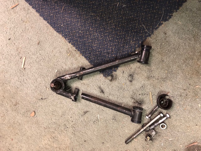
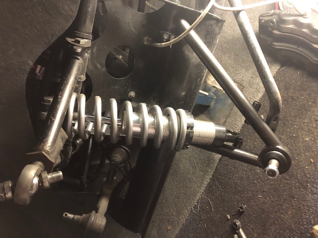
 Broken A-Arm
Hi Everyone,
Recently during some track time at Phillip Island with the CCCV I noticed my car would "move around a bit" especially at high speed on the straights 
It was a very gusty day and I put it down to that. Did a quick check in the pits and everything seemed ok.
But when I finished the day the steering felt a bit spongy.
Upon a detailed inspection when I got home I found I had a broken passenger side A-Arm. I think it might have been cracked or fractured prior to the event - I had done my pre-race check and didnt pick it up. So not sure.
I contacted Dan at Classic Revival and he made me two new A-Arms and installed new bushes and lower ball joint. All in a relatively short time. Thanks Dan for great service.
Installed them both tonight and did a quick front end alignment check - need to adjust by 2mm, road test and all good.
I reckon those potholes on Melb roads were the cause of this, I've done 30,000Klms over 10 years.
Anyway, here's some pics. Heading off to Winton next week weather permitting for a test day, should be fun.
cheers
Gregg

 |


 35Likes


 Threaded Mode

