 The goal
 for this setup was simple. To aquire the parts for a true bolt- on high- end EFI system, assemble it, tune it and run it
.. I didnt want to do any soldering, re-pinning or other EEC- geek work. If so, Id go with a Megasquirt or whatever and built the harness and all. This I had no time for
.. On this setup, the harness is 100% correct even down to the numbering on the harness telling what cylinder the coil and injector connector goes to. In other words, it should be pretty foolproof.
This setup use parts from the later Explorer 302 (1999- 2001) to mate up with the XFI/ XIM system for a 4.6 2V mod engine. The cam and crank trigger pattern are identical (1 for each 2 crank rotations and 36-1 crank wheel), and the fireing order are the same on the 4.6 and the 302HO and 351W.
There are other ways to do this, but those would require some of the work mentioned above. Other ways may also give a better or poorer result. I cannot say because I do not have the knowledge nor the experience. Some say a 4 tooth crank trigger like the FAST would be better than the 36-1 in this install, that a hall sensor would be better than a discreet and so on
..
This applies to the 302W and 351W. However, with the 351 you will have to either modify a 302 or find other solutions for a cam position sensor and may be crank trigger wheel as well. More on this can be found on corral.net, in the aftermarket (AEM) EFI- section (see below).
The following applies to the Ford 302 8.2 deck height (or should I rather say 302 distributor height) block and the most of it also to the 351W, except for what previously said above.
First you need to have a 351 or 302 HO (79- 93 FOX efi) fire order camshaft in your block. That is because the XIM ignition use this fire- order.
Youll also need throttle body, manifold with injector bungs , injectors, rails and the rest of the fuel system which might be factory Ford or any aftermarket types.
This is the list of hardware parts youll need, with some remarks:
XFI box FST-301003 (This is the one with internal datalogging, which you might not need.)
XIM box with coil harness FST-301313A
Main harness FST-301100
Injector harness FST-301203 Have EV1 injector connectors
Coils FST-30256-8
TPS sensor FST-307005 (or you can use factory Ford and put on new pins and connector to mate with the harness).
Crank sensor SMP-PC325
Crank trigger wheel/ damper RNB-594-155 (You only need the trigger wheel.)
Engine front cover RNB-635-106
Cam sensor RNB-689-101 This use the large ID 302 distributor gear!
IAC valve FST-307014 (GM style)
IAC adapter FST-307022 (adapter for Ford TB to GM IAC)
Air temp sensor FST-307004 (GM style)
Water temp sensor FST-307003 (GM style)
MAP sensor FST-307007 (to suit; 1,2,3 or 5 bar
this is a 1 bar sensor for N/A)
Ignition wires TAY-84044 These are quite short
.
Other remarks:
These part numbers are Summits. Parts can be obtain from FAST, Rockauto,
.
Edelbrock /Weber marelli Pico style injectors will fit the connectors in the injector harness.
The trigger wheel might be obtained from a salvage yard, from a 5.0 Explorer or other. This, ofcourse, also applies to the other sensors and the front cover
You also need this custom fabricated piece:
Disc, steel. Damper snout OD and Explorer trigger wheel ID (press fit).
You will also need to figure out how/ where to place your coils and fabricate or buy the necessary parts like a coil bracket.
Extras: FAST is offering a lot of extras to the XFI; turbo boost handling,
oil pressure logging, traction control, boost control, nitro control
.. You can pick from the list. Read up at
FAST online
Install:
Its much plug & play here. My engine fired up at first try, so it cant be much to it
You might remove the crank trigger wires on the main harness, since it will go onto the XIM harness. Splice & ground. The harness(es) is great in many instances. Only concern is that theyre very long & bulky. In my small car the boxes could go into the trunk
. Take your time and figure where to place the boxes and how to route the harness.
Be sure to let the coil harness be routed by itself. I used a hi-ram manifold and put all wireing inbetween the runners/ cylinder banks less the ignition wires which I ran on the valve covers.
Cam position sensor should be installed with the tool that comes with it; put engine in TDC, put the tool on to lock the sensor in place and slide it in & lock the bolt down. It will be in the correct spot, trust me
On installing the crank trigger wheel, first note at what crank degree the missing tooth is mounted on the balancer. Install the fabricated adapter to your crank balancer and then slide on the trigger wheel and make sure the missing one falls where it should
. I seem to remember its around the 30 ATDC, but dont take my word for it
One more thing on the balancer and so
My timing pointer got in conflict with the crank sensor on the front cover. I cut some and welded some and it came out good. You have to make sure the timing pointer is DEAD ON! Very important. So please check with true TDC, balancer and pointer at mock- up
.
The main trouble I had, after running the engine for a couple of weeks, was the balancer and how the crank trigger wheel was sitting in regards to the front cover. On engine mock- up the balancer was installed and bolt torqued to spec. (90 ftlbs?). However- it did not seat to the crank gear. SO PLEASE CHECK THIS ON EVERY INSTALL! This was an Eagle crank and a summit SFI balancer. Eventually crank bolt got loose and it could be further torqed, ending up squeezing trigger wheel between balancer and front cover. The solution to this was to install a spacer between balancer and crank gear- a sleeve on the crank snout. Take a look at the forum at the corral for more on this.
Then its time for the tuning
Please read all relevant information in the C-COM help section. Here you find a walk- through on how to initially set your software settings as well as more fine- tuning tips & tricks, some unique for the FAST XFI system.
Heres a quick walk- through on first startup checks:
Check your fuel pressure. Should be 46 at no vacuum.
Set fuel, relative to your injector size, at a sensible level in your idle- area. Say 800- 1200 rpm and 40- 100 LOAD or MAP. I have around 15 with 44lbs injectors.
Set timing in the same area to 16- 20 degrees.
Do all the checkbox things for this setup and then finally, before you attempt to fire, put in your operational parameters file in system configuration fixed timing test mode and set fixed timing test advance to 20 degrees.
Now; fetch your good old timing light and hook it up. Fire up the engine. If it does not start, make adjustments to IAC open VS CTS and cranking fuel until it fires. (If fuel horrible fuel smell, take off fuel
etc.)
Your timing light should now show 20 degrees. If not, make adjustments in the crank ref. angle (*BTDC) in the operational parameters to get it exactly at 20 degrees.
Now, as the engine is running at idle (hopefully!), remove the MAP vacuum connection (close inlet man. Hole) and check fuel pressure which should be 46 lbs. Adjust to this figure.
Tuning:
Now its time to beginning filling in the tables
. Get the engine up to temps (160F+) and get it to idle smoothly before you move on. Be SURE that the AE fuel vs CTS is 0 at this point. Add or take away fuel on the surrounding cells to get the appropriate AF- number at anywhere between 15 and 13.5. By adjusting TB opening and fuel, get the IAC down to 10 and recalibrate the TPS.
Make a preliminary fuel and spark map from what you now have. On fuel you should have the lowest AF- numbers where your max torque is. Check you cam specs/ ask you manufacturer or use compareable dyno graphs to get an idea. Let the fuel rise steady into this area an keep it up top.
For spark you can use your knowledge on what a compareable distributor advance would be like and start there. Of course there will be a lot different with a pressurized engine with turbo or supercharger, so you better read up on this
. Also, due to the nature of a high- pressure boosted setup, the only way to tune such a setup is on a dyno/ rolling road. Be careful with the timing
Ive tuned a N/A pump- gas setup with a fairly large cam and Ive ran into one big problem: The engine was doing changes in RPM, up-down- up- down, even if my throttle was stationary and everything else seemed
not moving, on slow running in 1. and 2 gear around 1800- 3000 rpms. This condition might be due to the cam and inlet combination. All other tuning have gone relatively well. Getting cold temp fuel addition and AE fuel vs TPS rate can be some time consuming as well, but its fairly quick to get to good results.
Theres a lot to be said on tuning and the different parameters in the C-COM software.
I do not wish to go further into these. My guidelines are as follows:
- Read the HELP- sections in the C-COM software. Search whenever you have a question. Its usually in the HELP- file although you cannot remember where to find it
.
- Use the FAST online tech forum for help on setup or tuning issues. There are a lot of helpful and skilled persons there. Heres the complete webadress to take you right there:
Fast product support
- Other useful online resources:
EFI101
Corral aem-ems forum/ (heres some pics on the crank trigger setup as well.)
+ a bunch of others
..
I take absolutely no responsibility of errors and utterly wrong statements in the txt above...
If you have any questions you can post here or send me a PM.
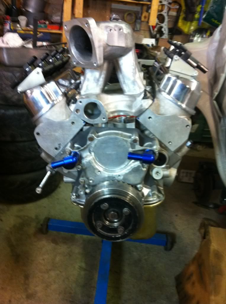
Sorry for the blurry pic...
Regards
RS


 Linear Mode


