Club Cobra GasN Exhaust  

Go Back   Club Cobra > Engine Building, Tuning, and Induction > Small Block Talk

MMG Superformance
Nevada Classics
MMG Superformance
Main Menu
Module Jump:
Nevada Classics
Nevada Classics
Keith Craft Racing
Keith Craft Racing
Advertise at CC
Banner Ad Rates
Keith Craft Racing
MMG Superformance
MMG Superformance
April 2024
S M T W T F S
  1 2 3 4 5 6
7 8 9 10 11 12 13
14 15 16 17 18 19 20
21 22 23 24 25 26 27
28 29 30        

Kirkham Motorsports

Like Tree1Likes
  • 1 Post By Texasdoc

Reply
 
LinkBack Thread Tools Rate Thread Display Modes
  #1 (permalink)  
Old 07-08-2014, 08:10 PM
Texasdoc's Avatar
CC Member
Visit my Photo Gallery

 
Join Date: Feb 2012
Location: Keller, TX
Cobra Make, Engine: Lonestar Classics LS427. Self-built 408W, AFR 195 heads, Performer RPM Intake, Quick Fuel 750, 407rwhp, 479rwtq
Posts: 549
Not Ranked     
Default Installing 5.0 Mustang Alternator (2G)

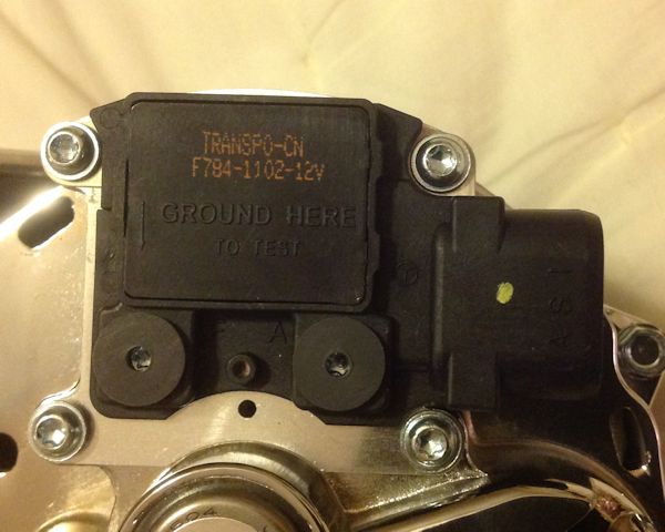
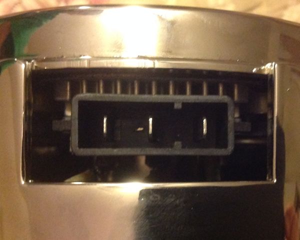
Building a 408 and am about ready to install the alternator. Previous engine has a 1g with external voltage regulator. New alternator I bought is a 2g with internal regulator. I thought I was buying one with open terminals, but I got one for a fox body mustang. This alternator has two connectors. One is labelled with I, S, and A. The other is not labelled but has three connectors. There is also a ground connect.

I don't have a fox body mustang and cannot figure out what connectors get wired to my painless harness (or I can run new wires).

Connector 1


Connector 2


Connector 1 has I, S, and A. I goes to switched battery power. S and A I'm not sure. There is also a F and A spot on the square box but these look like voltage terminal ports, not connectors.

Connector 2 has three connectors. None are labelled. I think one of these goes to the battery + terminal but I'm not sure which one. The other two, not sure about.

Anyone know how to wire this?

Thanks. Tom

Last edited by Texasdoc; 07-08-2014 at 08:21 PM..
Reply With Quote
  #2 (permalink)  
Old 07-08-2014, 08:14 PM
Texasdoc's Avatar
CC Member
Visit my Photo Gallery

 
Join Date: Feb 2012
Location: Keller, TX
Cobra Make, Engine: Lonestar Classics LS427. Self-built 408W, AFR 195 heads, Performer RPM Intake, Quick Fuel 750, 407rwhp, 479rwtq
Posts: 549
Not Ranked     
Default

Ok, found some pigtails that go into these connectors, but still no idea on where they all connect.

7520E has three connectors. The two bigger black wires should go to battery. The small gray - don't know.
7520F has three small wires. Green, gray, and yellow.


Guess that the yellow wire on 7520F goes to the gray wire on 7520E.

Last edited by Texasdoc; 07-08-2014 at 08:39 PM..
Reply With Quote
  #3 (permalink)  
Old 07-08-2014, 08:55 PM
Texasdoc's Avatar
CC Member
Visit my Photo Gallery

 
Join Date: Feb 2012
Location: Keller, TX
Cobra Make, Engine: Lonestar Classics LS427. Self-built 408W, AFR 195 heads, Performer RPM Intake, Quick Fuel 750, 407rwhp, 479rwtq
Posts: 549
Not Ranked     
Default

Found this for a 2G alternator. It seems to have all the right connectors. Is this right?

Can I use 130 amp fuse instead of the fuse links? If I don't have an idiot light, can I just connect I to switched power without the light or resistor?

Connector 1:
I - switched power
S - to small gray wire on connector 2
A - (voltage sensor wire) - Connect to main wiring harness after Max fuse. Senses voltage at main bus.

Connector 2:
2x Large black - to battery (or powered terminal on starter relay) - fused
Small gray - to S on connector 1 (why is this not connected internally??)


Last edited by Texasdoc; 07-08-2014 at 09:00 PM..
Reply With Quote
  #4 (permalink)  
Old 07-12-2014, 03:36 PM
Texasdoc's Avatar
CC Member
Visit my Photo Gallery

 
Join Date: Feb 2012
Location: Keller, TX
Cobra Make, Engine: Lonestar Classics LS427. Self-built 408W, AFR 195 heads, Performer RPM Intake, Quick Fuel 750, 407rwhp, 479rwtq
Posts: 549
Not Ranked     
Default

Nobody knows how to wire this alternator? Hello... is this thing on...??
RockBit likes this.
Reply With Quote
  #5 (permalink)  
Old 07-12-2014, 03:44 PM
jhirasak's Avatar
CC Member
Visit my Photo Gallery

 
Join Date: Feb 2012
Location: Redondo Beach, CA
Cobra Make, Engine: 331 SB, AFR heads
Posts: 75
Not Ranked     
Default

Texasdoc,

I think that you are doing fine by yourself and do not need a lot of inputs from the peanut gallery. What you have posted is more information than I have, so I am learning from your experience.

John

Last edited by jhirasak; 07-12-2014 at 08:29 PM.. Reason: correct spelling
Reply With Quote
  #6 (permalink)  
Old 07-12-2014, 05:07 PM
jhirasak's Avatar
CC Member
Visit my Photo Gallery

 
Join Date: Feb 2012
Location: Redondo Beach, CA
Cobra Make, Engine: 331 SB, AFR heads
Posts: 75
Not Ranked     
Smile

Texasdoc,

The 2G diagram that you have provided is the one that you need to wire your car.

The proper connectors for a 2G alternator are 7502E and 7502F. The 7502E should connect to Connector 2 on the alternator and the 7502F should connect to Connector 1 on the alternator. The connectors should be keyed so they will only connect in the proper orientation.

I would recommend that you use two fuse links as indicated since the wires are individually sized to only carry approximately half of 130 amps.

I would recommend that you install an indicator lamp as indicated on the circuit diagram with the proper resistance. You can wire it without a lamp but you may not know if you have a failure in the alternator if it should happen.

The grey wires on each connector should be coupled together. Since the alternators are built to either support an internal regulator or an external regulator, the choice of connection to the stator input is through the connector wiring.

See, I told you that you already had all of the necessary information on hand.

Let me know if you have any questions.

John
Reply With Quote
  #7 (permalink)  
Old 07-12-2014, 07:04 PM
Texasdoc's Avatar
CC Member
Visit my Photo Gallery

 
Join Date: Feb 2012
Location: Keller, TX
Cobra Make, Engine: Lonestar Classics LS427. Self-built 408W, AFR 195 heads, Performer RPM Intake, Quick Fuel 750, 407rwhp, 479rwtq
Posts: 549
Not Ranked     
Default

Quote:
Originally Posted by jhirasak View Post
Texasdoc,

I think that you are doing fine by yourself and do not need a lot of inputs from the peanut gallery. What you have posted is more information that I have, so I am learning from your experience.

John
I like peanuts!

Question about the indicator light - what light do I use? Any standard 12v bulb? I think the 510ohm resistor is so that the circuit will still get activated if the bulb burns out. If the bulb burns out and there is no accessory pathway, the I circuit never gets power.

So, any 12v dash light?
Reply With Quote
  #8 (permalink)  
Old 07-12-2014, 08:27 PM
jhirasak's Avatar
CC Member
Visit my Photo Gallery

 
Join Date: Feb 2012
Location: Redondo Beach, CA
Cobra Make, Engine: 331 SB, AFR heads
Posts: 75
Not Ranked     
Default

The resistor is there to balance the load across the alternator indicator lamp. To find out the required wattage for the bulb, just go to an auto parts store and ask for a bulb that fits the Mustang that has a 2G alternator in it.
Reply With Quote
  #9 (permalink)  
Old 07-15-2014, 07:27 AM
jhirasak's Avatar
CC Member
Visit my Photo Gallery

 
Join Date: Feb 2012
Location: Redondo Beach, CA
Cobra Make, Engine: 331 SB, AFR heads
Posts: 75
Not Ranked     
Default

Texasdoc,

By the way, there is another cable that I would recommend that you install that is not indicated on the 2G circuit diagram. You will notice that one side of the diodes are indicated as going to ground inside the alternator. Normally, the mechanical attachment of the alternator case to the engine block is sufficient to complete the circuit to the battery. However, I would connect a ground strap from the ground terminal on the alternator to the engine block ground attachment point as a means to insure that your installation is electrically complete. I realize that this is a bit of a belts and suspenders approach but I would be more comfortable if you did so.

Regards,

John
Reply With Quote
  #10 (permalink)  
Old 07-15-2014, 08:00 AM
Texasdoc's Avatar
CC Member
Visit my Photo Gallery

 
Join Date: Feb 2012
Location: Keller, TX
Cobra Make, Engine: Lonestar Classics LS427. Self-built 408W, AFR 195 heads, Performer RPM Intake, Quick Fuel 750, 407rwhp, 479rwtq
Posts: 549
Not Ranked     
Default

Yes, thanks jhirasak. I have a 8g wire going from the alternator case to the engine block to ensure a good ground. My alternator has a connector/post for just this reason.

Quote:
Originally Posted by jhirasak View Post
The resistor is there to balance the load across the alternator indicator lamp. To find out the required wattage for the bulb, just go to an auto parts store and ask for a bulb that fits the Mustang that has a 2G alternator in it.
If I don't want/need the indicator light, can I just wire the I terminal to switched hot and delete the indicator light portion of the diagram?

Last edited by Texasdoc; 07-15-2014 at 08:18 AM..
Reply With Quote
  #11 (permalink)  
Old 07-15-2014, 10:08 AM
jhirasak's Avatar
CC Member
Visit my Photo Gallery

 
Join Date: Feb 2012
Location: Redondo Beach, CA
Cobra Make, Engine: 331 SB, AFR heads
Posts: 75
Not Ranked     
Default

If you delete the light, I would recommend that you either install an ampmeter or a voltmeter in your charging circuit to provide you with information regarding the status of your battery as well as the performance of your alternator. If you already have one of those on your car, I would consider it appropriate to delete the indicator light.

John
Reply With Quote
  #12 (permalink)  
Old 07-16-2014, 01:56 PM
CC Member
Visit my Photo Gallery

 
Join Date: Aug 2010
Cobra Make, Engine: Lone Star with IRS, 427W with megasquirt, T56 magnum
Posts: 309
Not Ranked     
Default

If you don't use the light, install it under the dash. When the engine isn't running, the alternator grounds it's side of the light. If you wired it direct to hot, you'll burn something up. If the light REALLY offends you, use a 50 ohm resistor.

The yellow wire can be wired directly to the output terminal but only if you run 6ga wire all the way to the battery. That wire senses the actual charge voltage. If your wire and fusable link is a little long or light, there will be a voltage drop. This sense wire allows the alternator to put out a little more voltage to compensate for the voltage drop fromt he alternator to the battery.

What I did to clean things up was run my output wire directly to the starter. If you're running the old school starter with the solenoid on the fenderwell instead of the solenoid integral to the starter, you'll can't do that. If you have a modern gear reduction starter with the battery going directly to it, it's a perfect place to put the juice to.
Reply With Quote
  #13 (permalink)  
Old 07-16-2014, 07:34 PM
Texasdoc's Avatar
CC Member
Visit my Photo Gallery

 
Join Date: Feb 2012
Location: Keller, TX
Cobra Make, Engine: Lonestar Classics LS427. Self-built 408W, AFR 195 heads, Performer RPM Intake, Quick Fuel 750, 407rwhp, 479rwtq
Posts: 549
Not Ranked     
Default

That makes sense. I wonder if I can install a 12v buzzer instead of the idiot light under the dash. I have a voltmeter on the dash and don't have room for another light without cutting another hole. A buzzer would let me know if there is a problem. I know I can find those practically anywhere.

I do have the new starter that has the solenoid built in. I'm going to run the hot wires to that. It goes directly to the battery from there.

If the yellow wire is the sense wire, does that need to go to the battery, or can it go to the power bus under the dash to make sure the electronics are getting a good 12+ volts?
Reply With Quote
  #14 (permalink)  
Old 07-17-2014, 04:23 AM
CC Member
Visit my Photo Gallery

 
Join Date: Aug 2010
Cobra Make, Engine: Lone Star with IRS, 427W with megasquirt, T56 magnum
Posts: 309
Not Ranked     
Default

I wouldn't put the sense wires on the buss. If there's a little voltage drop between the buss and battery, the alternator will sense it and compensate, and dry out your battery with excess voltage. This will also make your alternator work itself to death in the process. If you have meaty #2 or better from the starter to the battery, you can get away with sensing there.

A buzzer should be fine as long as it's less than 1/2 amp or so, but it will buzz every time you turn on the ignition until the engine is running. A light bulb under the dash somewhere (you don't need to see it)(maybe zip tied to the column) or a resister may be easier on your nerves.
Reply With Quote
  #15 (permalink)  
Old 10-09-2014, 02:00 PM
Texasdoc's Avatar
CC Member
Visit my Photo Gallery

 
Join Date: Feb 2012
Location: Keller, TX
Cobra Make, Engine: Lonestar Classics LS427. Self-built 408W, AFR 195 heads, Performer RPM Intake, Quick Fuel 750, 407rwhp, 479rwtq
Posts: 549
Not Ranked     
Default

Finally actually doing the wiring. The heat and mosquitos have kept me out of the garage this summer.

Going thru my tool kit, I found a 470 ohm resistor. Is this going to be "close enough" or do I need to go buy a pack of 510 ohm resistors?
Reply With Quote
  #16 (permalink)  
Old 11-21-2014, 02:18 PM
Texasdoc's Avatar
CC Member
Visit my Photo Gallery

 
Join Date: Feb 2012
Location: Keller, TX
Cobra Make, Engine: Lonestar Classics LS427. Self-built 408W, AFR 195 heads, Performer RPM Intake, Quick Fuel 750, 407rwhp, 479rwtq
Posts: 549
Not Ranked     
Default

For the record, the 470ohm resistor works so far. I haven't burnt out the bulb to test the flow thru the resistor, but with the resistor and bulb, it functions as it should.

I have the new starter that has a built in solenoid. I put the sense wire there. The power wires from the alternator to the starter are each 10 guage with the fusable links. There is a large 2/0 guage wire running from there to the battery.
Reply With Quote
Reply

Thread Tools
Display Modes Rate This Thread
Rate This Thread:

Posting Rules
You may not post new threads
You may not post replies
You may not post attachments
You may not edit your posts

BB code is On
Smilies are On
[IMG] code is On
HTML code is Off
Trackbacks are On
Pingbacks are On
Refbacks are On


All times are GMT -7. The time now is 03:12 PM.


Powered by vBulletin® Version 3.8.0
Copyright ©2000 - 2024, Jelsoft Enterprises Ltd.
Search Engine Friendly URLs by vBSEO 3.6.0
The representations expressed are the representations and opinions of the clubcobra.com forum members and do not necessarily reflect the opinions and viewpoints of the site owners, moderators, Shelby American, any other replica manufacturer, Ford Motor Company. This website has been planned and developed by clubcobra.com and its forum members and should not be construed as being endorsed by Ford Motor Company, or Shelby American or any other manufacturer unless expressly noted by that entity. "Cobra" and the Cobra logo are registered trademarks for Ford Motor Co., Inc. clubcobra.com forum members agree not to post any copyrighted material unless the copyrighted material is owned by you. Although we do not and cannot review the messages posted and are not responsible for the content of any of these messages, we reserve the right to delete any message for any reason whatsoever. You remain solely responsible for the content of your messages, and you agree to indemnify and hold us harmless with respect to any claim based upon transmission of your message(s). Thank you for visiting clubcobra.com. For full policy documentation refer to the following link: CC Policy
Links monetized by VigLink