 
 Main Menu
|
|
Nevada Classics
|
|
Advertise at CC
|
| S |
M |
T |
W |
T |
F |
S |
| |
|
|
1 |
2 |
3 |
4 |
| 5 |
6 |
7 |
8 |
9 |
10 |
11 |
| 12 |
13 |
14 |
15 |
16 |
17 |
18 |
| 19 |
20 |
21 |
22 |
23 |
24 |
25 |
| 26 |
27 |
28 |
29 |
30 |
|
|
|
|
CC Advertisers
|
|
 1Likes 1Likes

10-17-2014, 01:41 PM
|
|
CC Member

|
|
|
Join Date: Feb 2003
Location: Jonesboro GA,
Posts: 382
|
|

 Not Ranked
Quote:
Originally Posted by J.Jensen

What have you done up front to keep it down as well at high speeds? The car has a full aero package, but without major body modifications.Do you have any calculations on your diffusor on what speed it becomes effective at? Yes
|
I really don't want to turn this into a thread for my build. I'll post details after all mockup is complete and I'm working on final assembly. For now, I'm just looking for pictures of race cars with modified side vents.
Thanks,
Mike |
10-17-2014, 05:15 PM
|
 |
CC Member
|
|
|
Join Date: Apr 2005
Location: Tucson,
AZ
Cobra Make, Engine:
Posts: 5,391
|
|
Not Ranked
Here's an Austin Healey with a side vent I was referring to earlier. Looks pretty nice on the car IMO.
Larry

__________________
Alba gu bràth
Last edited by LMH; 10-17-2014 at 05:22 PM..
|
10-17-2014, 05:22 PM
|
|
CC Member
|
|
|
Join Date: Apr 2005
Location: Tucson,
AZ
Cobra Make, Engine:
Posts: 5,391
|
|
Not Ranked
Of course, the ultimate in side vent!

__________________
Alba gu bràth
|
10-17-2014, 06:14 PM
|
|
Senile Club Cobra Member
|
|
|
Join Date: Feb 2001
Location: Buffalo, NY USA,
NY
Cobra Make, Engine: Superformance
Posts: 4,573
|
|
Not Ranked
"Aero" and "Cobra" are oil and water, they don't mix.
__________________
"I'm high all right, but on the real thing....powerful gasoline and a clean windshield..."
rick@autoventureusa.net
|
10-17-2014, 07:10 PM
|
|
CC Member
|
|
|
Join Date: Feb 2003
Location: Jonesboro GA,
Posts: 382
|
|
Not Ranked
Quote:
Originally Posted by Mark IV
"Aero" and "Cobra" are oil and water, they don't mix. |
True, unless you know enough to understand how emulsifiers work. |
10-18-2014, 12:54 AM
|
|
CC Member
|
|
|
Join Date: Apr 2014
Posts: 103
|
|
Not Ranked
Depending on the level of "aero", if its tight enough all way round from splitter in front to diffusers in the rear, having air vent to under the car from a ram fed engine bay might reduce the suction effect under the car a little?
|
10-18-2014, 02:45 AM
|
 |
CC Member
|
|
|
Join Date: Jan 2001
Location: Cape Coral,
FL
Cobra Make, Engine: 2009 Solbra
Posts: 3,861
|
|
Not Ranked
 Csx2080
__________________
Dan Wulff
I carry a gun because a cop is too heavy.
(No doubt, most will blame it on the donuts.)
You're just jealous because the voices only talk to me
Earth is the insane asylum for the universe.
The gene pool could use a little chlorine.
The original point and click interface was a Smith & Wesson.
|
10-22-2014, 10:56 PM
|
|
CC Member
|
|
|
Join Date: Sep 2012
Location: Portland,
OR
Cobra Make, Engine: ERA - B2Motorsports Dart 331
Posts: 464
|
|
Not Ranked

Nice - some questions -
Why did you elect to tip the rad back. It appears you are using a rear exit diffuser on the rad exhausting thru the hood (similar to the Daytona). I ask because I am working on re mounting my radiator and right now have it mocked up with the rad tilted forward similar to Ken Miles 390. With your setup it seems the air will be headed down before slamming into a parallel wall before it figures out how to change to a vertical direction. It seems this could cause high pressure, possibly back feeding thru the rad.
I originally headed down this road but I saw a GT40 over the summer and noticed how they ducted the air. Though they do slam it into a nearly vertical wall, the direction of the air out of the rad is up. Digging thru some books, I found some pictures of the Turd under construction and that got me thinking. It seemed interesting the Daytona also had the rad tipped forward. I purchased a book on CAN-AM cars and none I have seen mounted the rad tipped back. It seems by the end they would mount the rad and the duct would attach normal to the surface of the rad and then smoothly blend back into the body and the free stream.
1967 - ducting very similar to GT40

Circa 73 74 - M8E - much smoother

MK II

MK IV - looks like they were trying to get smooth flow over the windshield
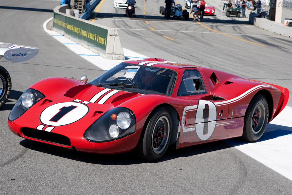
Am I seeing this correctly? Does your rad get fully shrouded and then exhaust out the top or is the upper alum bits for intake? If you are going out the bottom and depending on how fast you want to go, you should re-consider - you have everything right where you need it. 
The lower duct is interesting - oil cooler? - how (where) will you vent it?
Your work is intriguing -
Miles 427
x-chr
Last edited by ERA2076; 10-22-2014 at 11:04 PM..
Reason: Add Pic
|
10-23-2014, 04:35 AM
|
|
CC Member
|
|
|
Join Date: Feb 2003
Location: Jonesboro GA,
Posts: 382
|
|
Not Ranked
The lower duct is a ram air system. The ram air intake plenum is Kevlar, and is a true divergent cone that has an approximate 33sq in cross section at the front and gradually increases to a 36sq in cross section where it feeds twin 5" tubes to a ram air box on top of the motor. The ram air box contains a 14x5 round air filter and sits on top of a 1200cfm throttle body injection. The entire system is designed such that the cross section (inside volume) gradually increases up to the throttle body. This increase in cross section causes the air to gradually slow and pressure to rise as it approaches the throttle body. Oil temperature control is handled with an oil/water heat exchanger.
RE radiator angle: Heat exchanger core placement within a duct is a complex issue with no easy answer, conversely, one mounting direction is not inherently superior to another as everything is contained within the duct. This design was driven by the stock 427 radiator opening of about 220sq in.
Heat exchanger core size is determined by calculating the percentage of core that is blocked, and upsizing to have at least 220sq of open space. It just so happens that Gordon Levy's racing radiator was just about right. Having the core angled allows for a smaller divergent duct on the intake side. The heat exchanger packaging restrictions determined mounting angle direction. Mounting the heat exchanger perpendicular to airflow necessitates either too radical a divergent duct for the large core, or too small a core for proper flow. It is very rare that a proper heat exchanger would be mounted perpendicular to airflow. Simply making the core thicker may give more surface area, but it will also restrict flow through the duct.
In this design, I had some packaging restrictions. The short nose and X brace on the frame limited options for heat exchanger exit duct location and angle. This dictated that the lower section of the heat exchanger core be forward. This design has a divergent duct from the intake to the heat exchanger core, and then a convergent duct to the hood exit. The hood exit has the same cross section as the intake.
Here is a design concept sketch. You can see more details at ffcars, but I don't really want to do a build thread on this site until later.


|
10-23-2014, 07:11 AM
|
 |
Senior Club Cobra Member
|
|
|
Join Date: Sep 2000
Location: Holderness, NH, US of A,
NH
Cobra Make, Engine: CSX 4772 old iron FE
Posts: 5,499
|
|
Not Ranked
The vent doors I posted a pic of allow air out the gap between footbox and body. It is one of the worst places for hot underhood air to get into the cockpit, hence the louvres and their location. Thanks Larry I knew they were Dunlop but hadn't nailed down their donor. It looks like the new lightweights are using them.
|
10-23-2014, 08:01 AM
|
 |
CC Member
|
|
|
Join Date: Oct 2004
Cobra Make, Engine: CSX2321
Posts: 1,368
|
|
Not Ranked
Quote:
Originally Posted by LMH
Some Austin Healey's were modified with a vent behind the front wheels. Kind of nice looking in a sort-of-triangular style. I can look for a couple pics later.
Larry
|
 |
10-23-2014, 09:10 AM
|
|
CC Member
|
|
|
Join Date: Sep 2012
Location: Portland,
OR
Cobra Make, Engine: ERA - B2Motorsports Dart 331
Posts: 464
|
|
Not Ranked
Thanks - now I see. The down side is lift i.e. low pressure on top of the hood with the high pressure at the intersect of the rad to the roof wall, but a much reduced surface area compared to a stock cobra and your nozzle is really cool. If you could tip it forward you could put a floor in and the roof area is minimized. The air pressure will sit on the intake tract floor (possible down force) with pressure escape thru the roof i.e. rad . This greatly reduces the static pressure area on the intake tract roof.
In theory a shorter rad with thicker core could provide needed cooling surface area while allowing for more flexible packaging, but its a lot of work to find out it won't cool .
Will you will block off the rest of the front of the nose?
Is the air box, tract, and radiator sized to the volume needed to charge the engine?
Love your nozzle - wish there was away to package them not so steep. I have considered a shorter rad with thicker core that would provide needed cooling surface area while allowing for more flexible packaging, but its a lot of work to find out it won't cool . 
I agree with you - it is not a straight forward endeavor. It seems all one can do is build,test, and then rebuild - 
Appreciate your work and sharing your thoughts.
x-chr
|
10-23-2014, 06:00 PM
|
|
CC Member
|
|
|
Join Date: Feb 2003
Location: Jonesboro GA,
Posts: 382
|
|
Not Ranked
Quote:
Originally Posted by ERA2076
[IMG][/IMG]
Thanks - now I see. The down side is lift i.e. low pressure on top of the hood with the high pressure at the intersect of the rad to the roof wall, but a much reduced surface area compared to a stock cobra and your nozzle is really cool. If you could tip it forward you could put a floor in and the roof area is minimized. The air pressure will sit on the intake tract floor (possible down force) with pressure escape thru the roof i.e. rad . This greatly reduces the static pressure area on the intake tract roof.
In theory a shorter rad with thicker core could provide needed cooling surface area while allowing for more flexible packaging, but its a lot of work to find out it won't cool .
Will you will block off the rest of the front of the nose?
Is the air box, tract, and radiator sized to the volume needed to charge the engine?
Love your nozzle - wish there was away to package them not so steep. I have considered a shorter rad with thicker core that would provide needed cooling surface area while allowing for more flexible packaging, but its a lot of work to find out it won't cool .
I agree with you - it is not a straight forward endeavor. It seems all one can do is build,test, and then rebuild -
Appreciate your work and sharing your thoughts.
x-chr |
Thanks for the kind words, however,I don't really know how to put it gently and also don't want to start an internet pissing match, so I just be blunt. Your assumptions are incorrect in regards to the potential for lift and heat exchanger flow characteristics.
Lift or down force with a heat exchanger within a sealed duct are essentially a non factor. Pressures will average out over the assembly with a net of zero. Obvious exception being the mass of air entering at one elevation and exiting at a different elevation and direction, and the effect of that air on surrounding aerodynamics. The only gain I would get from tilting the radiator in the opposite direction is the air flowing through the core currently moves downward 1" before moving back upwards and out the duct. No doubt there is some energy consumed with this movement, but not much. It's a bit more complicated, but think Newton's third law. Another way to think about it is an inflated balloon. Internal pressure is irrelevant with the exception of the area opposite the open nozzle.
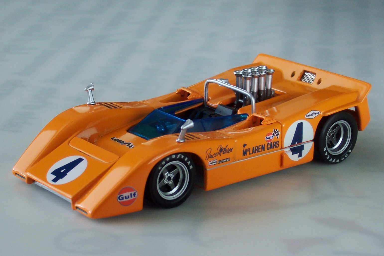
While small thick cores are still the topic of internet debate, thin heat exchangers at an acute angle are superior in terms of flow, cooling, and drag. This is why top F1 cars use the method. See pic below for an example
While the forward area of the hood is relatively low pressure, with a boundary separation device this will assist with duct evacuation. This eliminates an area of significant pressure differential on a stock cobra. Remember, the more lift you eliminate, the less downforce you need.
The premise of the build is to keep a relatively period correct look as compared to what was being raced in the late 60s so the front will not be blocked. Rather than harm the car's looks while attempting to redirect very high pressure air, the air is being allowed to flow through the car while being productive for cooling and a little downforce. On the other hand, the underside is getting the full treatment.
I'm not sure what you mean by nozzle, but thanks for the kind words. If you are talking about the ram air ducts, the angle isn't as acute as the photos make it look. If I don't get at least 50 hp from the system it will be a failure. While it may appear oversized, it is correct for the motor. The motor is an all aluminum 8,000rpm 432 Windsor with a 4" stroke, 235cc TEA ported twisted wedge R heads, Jesel shaft rockers, .700 solid roller, full custom equal length headers, and one massively ported Super Vic intake.
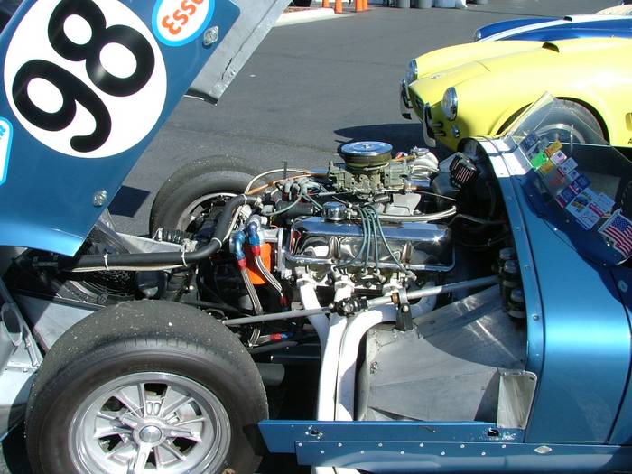
Here are some examples of proper heat exchanger plenum design. While designers tend to favor tilting forward, it isn't necessarily better and isn't always the case.

|
10-24-2014, 12:13 PM
|
|
CC Member
|
|
|
Join Date: Sep 2012
Location: Portland,
OR
Cobra Make, Engine: ERA - B2Motorsports Dart 331
Posts: 464
|
|
Not Ranked
In "Tune to Win" Smith addresses heat exchangers, duct components, and design.
My original design had the radiator tipped back. This necessitated a long roof and short bottom for the duct tract. This configuration dictates more roof than floor to act on. The roof of my duct was a piece of aluminum screwed into the inside roof of the nose. With the radiator tipped back there is some component of force acting up. Assuming the air is attached at speed, it should be very fast across the top of the nose with very low pressure. Though the force should equalize it is not acting on the same surface area.
The component of force acting up with the reduced pressure over the nose can cause lift. We are not talking about street speeds - my interest is in speed in excess of 130.
Please consider this - The engine compartment on a vehicle is a duct. Why do racers constantly try to relieve compartment pressure? 1) drag, 2) lift. The top of the duct is the hood and the road is the floor. The floor is immovable, but the ceiling( hood) is attached to the floor with springs and they will give. That give will take weight off of the front tires.
From my study I decided to see if I could tip the rad forward. The area of the 2.5" cored rad in my FIA @ 902 in^2. I found the rad dimensions for a GT40 MK1. They ran a 3: core at 956 in^2 of cooling surface. I taped together a card board box 14 X 25.75 X 3 (913 in^2) and configured it as cross flow. The box fits in the nose of the FIA tipped forward with a very short intake ceiling and a very long intake floor with the floor attached to the top of the frame rails.
In "Race Car Aerodyanamics" Katz shows 4 configurations of internal ducting. A vertical rad has the highest coefficient of velocity to the face, but also the highest drag. A forward tipped rad with vertical exhaust was quite low in drag, but also still high in velocity.
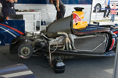
Here is an interesting Engineering Study on natural convection and the angle of a radiator. It was found that between 30-45 degrees the heat exchanger was more efficient because of the geometric relation of the fins to the air stream. Notice the angle of tip in the Red Bull car. Classes that can't run fans use this to their advantage. Conclusion Below.
Quote:
1. The heat transfer performance generally decreases with
the rise of the inclination angle. This decrease of heat
transfer performance is due to the blockage of un-
louvered fin and its reversed heat dissipating direction
against the raising air.
2. At an inclination angle such as 3045 a reversed trend
showing a considerable increase of heat transfer perfor-
mance is seen. This is because appreciable amount of air
flow was flowing across louver portion, causing a lou-
ver-directed" phenomenon as that in forced convection.
However, a further increase of inclination angle, the
blockage effect by the un-louvered fin is so strong as
to offset the louver-directed phenomenon.
3. Unlike those shown in force convection, the effect of the
number of tube row on the heat transfer performance
becomes more and more pronounced with the tempera-
ture rise. Generally the heat transfer performance
decreased with the number of tube row.
4. A correlation is proposed to describe the associated
influence of inclination angle. The correlation can
describe 71.4% of the experimental data within ±10%.
http://www.thaiscience.info/Article%...0exchanger.pdf
|
Here is a very interesting discussion of radiator angle with respect to F1
Radiator angle and aero balance - Forum - F1technical.net
Your diagram is mis-leading with respect to air flow. With the rad tipped back, what do you expect is happening to the air on the exit side at the bottom, middle, and top, knowing the air exiting the bottom has to pass the top of the rad?
I believe Ken Miles knew what he was trying to accomplish and it was replicated in the 390, 427 Flip, Daytona, and GT40 and countless Sport Racers since at least the mid 60's.
I am concerned about your intake feed. In Tune to Win" Smith discusses trying to pull cold air from down low. The air temperature at tarmac can be 20 degrees higher than the surrounding ambient air.
Provided the air is cold, the extra HP could be used to overcome the potential drag built into the system.
chr
|
10-24-2014, 02:53 PM
|
|
CC Member
|
|
|
Join Date: Feb 2003
Location: Jonesboro GA,
Posts: 382
|
|
Not Ranked
Quote:
Originally Posted by ERA2076
In "Tune to Win" Smith addresses heat exchangers, duct components, and design.
My original design had the radiator tipped back. This necessitated a long roof and short bottom for the duct tract. This configuration dictates more roof than floor to act on. The roof of my duct was a piece of aluminum screwed into the inside roof of the nose. With the radiator tipped back there is some component of force acting up. Assuming the air is attached at speed, it should be very fast across the top of the nose with very low pressure. Though the force should equalize it is not acting on the same surface area.
The component of force acting up with the reduced pressure over the nose can cause lift. We are not talking about street speeds - my interest is in speed in excess of 130.
Please consider this - The engine compartment on a vehicle is a duct. Why do racers constantly try to relieve compartment pressure? 1) drag, 2) lift. The top of the duct is the hood and the road is the floor. The floor is immovable, but the ceiling( hood) is attached to the floor with springs and they will give. That give will take weight off of the front tires.
From my study I decided to see if I could tip the rad forward. The area of the 2.5" cored rad in my FIA @ 902 in^2. I found the rad dimensions for a GT40 MK1. They ran a 3: core at 956 in^2 of cooling surface. I taped together a card board box 14 X 25.75 X 3 (913 in^2) and configured it as cross flow. The box fits in the nose of the FIA tipped forward with a very short intake ceiling and a very long intake floor with the floor attached to the top of the frame rails.
In "Race Car Aerodyanamics" Katz shows 4 configurations of internal ducting. A vertical rad has the highest coefficient of velocity to the face, but also the highest drag. A forward tipped rad with vertical exhaust was quite low in drag, but also still high in velocity.
Here is an interesting Engineering Study on natural convection and the angle of a radiator. It was found that between 30-45 degrees the heat exchanger was more efficient because of the geometric relation of the fins to the air stream. Notice the angle of tip in the Red Bull car. Classes that can't run fans use this to their advantage. Conclusion Below.
Here is a very interesting discussion of radiator angle with respect to F1
Radiator angle and aero balance - Forum - F1technical.net
Your diagram is mis-leading with respect to air flow. With the rad tipped back, what do you expect is happening to the air on the exit side at the bottom, middle, and top, knowing the air exiting the bottom has to pass the top of the rad?
I believe Ken Miles knew what he was trying to accomplish and it was replicated in the 390, 427 Flip, Daytona, and GT40 and countless Sport Racers since at least the mid 60's.
I am concerned about your intake feed. In Tune to Win" Smith discusses trying to pull cold air from down low. The air temperature at tarmac can be 20 degrees higher than the surrounding ambient air.
Provided the air is cold, the extra HP could be used to overcome the potential drag built into the system.
chr |
I guessing that you didn't catch that the drawing was a concept sketch. The lower heat exchanger air does not pass by the upper heat exchanger exit. Any idea the a long roof vs floor within a contained duct will generate lift is simply incorrect, but I'm quit comfortable with it and not really concerned with others opinions.
Regarding intake temps, you are correct, however, there isn't really any better place to do ram air on a cobra, and the opening already exists.
|
10-24-2014, 03:03 PM
|
|
CC Member
|
|
|
Join Date: Feb 2003
Location: Jonesboro GA,
Posts: 382
|
|
Not Ranked
I see that people just can't resist posting their ill informed opinions about my build. I'd like to point out that I simply was asking for pictures of modified side vents and have more than once mentioned that I'd like to avoid an aerodynamics debate, oh well, I guess this type of rude behavior is the norm in our modern society.
For the record, I never asked for an opinion of my build. I never asked for advice. I have better things to do than conduct debates with internet search engine experts. Most of all, to my core I don't give a damn what anybody on this forum thinks about what I am doing. If we ever meet at a show or on the track and you wish to share your unwelcome opinions in person, you will receive a clearer response.
So, does anyone have any pics of modified side vents?
Have a nice day.
|
10-24-2014, 05:11 PM
|
|
CC Member
|
|
|
Join Date: Apr 2008
Location: Near Chichester, Sussex by the sea......,
UK
Cobra Make, Engine: Crendon 427 S/C 428 FE+toploader
Posts: 668
|
|
Not Ranked
Not sure if i understand this thread, but the 427 Cobra here in the UK at the beaulieu motor museum has larger than average side vents. It was restored by Autokraft many years ago and features many odd non-standard items.
Some where i put up a bunch of pics on this on the web somewhere, but I can't remember where it was, and after 1/2 hr searching, can;t find them. But anyway here is someone else's pic...
Beaulieu Motor Museum |
10-24-2014, 05:42 PM
|
 |
Senior Club Cobra Member
|
|
|
Join Date: Jun 1999
Location: Fallbrook, CA USA,
CA
Cobra Make, Engine: Porsche 928 S4
Posts: 739
|
|
Not Ranked
mikeinatlanta,
It seems to me that you might wish to try the wonders of Photoshop as you are obviously only interested in visuals.
That way you can avoid being insulted by folk's "rude behavior" in their attempting to discuss your build.
And you can also avoid showing your sunny disposition to everyone on the internet.
|
10-24-2014, 09:28 PM
|
 |
CC Member
|
|
|
Join Date: Oct 2006
Cobra Make, Engine: Former owner of Long Live the Bow tie Contemporary #102 427 Chevy .30 over Merlin heads 11to1, TBI injection
Posts: 754
|
|
Not Ranked
I like the change from the "run like all the other sheep" thinking. If you like the larger side vents, and if you need there is some historical precedent then go for it! I like it , and unlike some of the exact number of rivets, same paint color of the 1965 championship season, and have to run (illegal and for good reason) Goodyear Billboards. Change can be good! And the new real AC car company put's GM engines in their new COBRA. Change.
|
10-25-2014, 05:19 AM
|
|
CC Member
|
|
|
Join Date: Feb 2003
Location: Jonesboro GA,
Posts: 382
|
|
Not Ranked
Quote:
Originally Posted by Richard Hudgins
mikeinatlanta,
It seems to me that you might wish to try the wonders of Photoshop as you are obviously only interested in visuals.
That way you can avoid being insulted by folk's "rude behavior" in their attempting to discuss your build.
And you can also avoid showing your sunny disposition to everyone on the internet.
|
Seems reading comprehension isn't one of your strong points. Like I said, I'm looking for pics of a cobra that was raced back in the 60's with enlarged side vents. It may not be obvious, but I don't really have an issue visualizing a concept and taking it through fruition.
I'll bet your one of those guys that likes critiquing other guys cars at the local cruise in. You probably get the same sunny disposition from them. Since you seem to be lacking in basic etiquette, let me explain. When someone asks your opinion or advice, feel free to give it. When someone is only sharing their car, say something nice, maybe ask a question, or STFU and move on.
|
 Posting Rules
|
You may not post new threads
You may not post replies
You may not post attachments
You may not edit your posts
HTML code is Off
|
|
|
All times are GMT -7. The time now is 04:11 AM.
Links monetized by VigLink
|


 Linear Mode


