Club Cobra
>
Manufacturers, Engine Builders, tools, and parts.
>
ERA---Speak with Bob Putnam
Goodbye Kansas
User Name
Remember Me?
Password
Portal
Register
FAQ
Community
For Sale
Gallery
Calendar
Today's Posts
Search
Community Links
Social Groups
Pictures & Albums
Contacts
Members List
Search Forums
Show Threads
Show Posts
Tag Search
Advanced Search
Go to Page...
Main Menu
Portal
Forums
Module Jump:
---------------
Active Topics
Advertising Rates
Journal
Nevada Classics
Advertise at CC
June 2026
S
M
T
W
T
F
S
1
2
3
4
5
6
7
8
9
10
11
12
13
14
15
16
17
18
19
20
21
22
23
24
25
26
27
28
29
30
CC Advertisers
·
Kirkham Motorsports
Superformance
·
Finish Line
·
Hurricane Motorsports
·
Serpent Express
·
·
Planet Cobra
·
Shell Valley Classic Wheels
·
Eight Stack Injection
12
Likes
Top
All
This Page
LinkBack
Thread Tools
Display Modes
Prev
Next
#
1
(
permalink
)
01-09-2014, 07:11 PM
ERA2076
CC Member
Join Date: Sep 2012
Location: Portland, OR
Cobra Make, Engine: ERA - B2Motorsports Dart 331
Posts: 464
Not Ranked
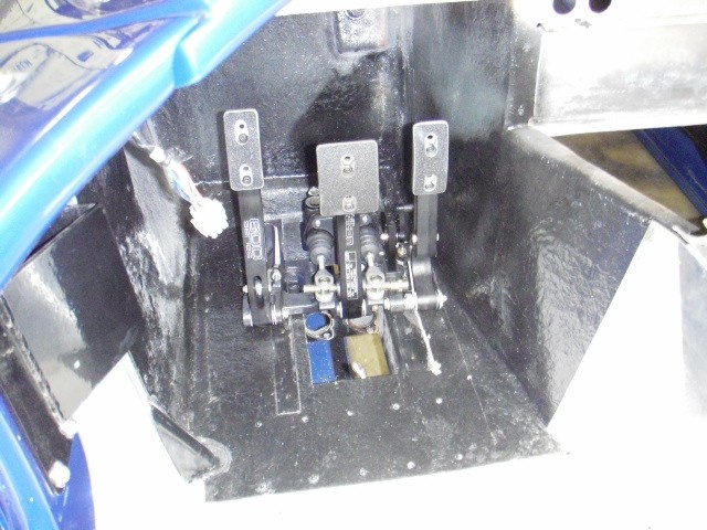
Goodbye Kansas
Tilton 600
My car will be worth 30 cents when we are done. With any luck it will be inspiring to drive
Last edited by ERA2076; 01-10-2014 at
04:52 PM
..
«
Previous Thread
|
Next Thread
»
Thread Tools
Show Printable Version
Email this Page
Display Modes
Switch to Linear Mode
Switch to Hybrid Mode
Threaded Mode
Posting Rules
You
may not
post new threads
You
may not
post replies
You
may not
post attachments
You
may not
edit your posts
BB code
is
On
Smilies
are
On
[IMG]
code is
On
HTML code is
Off
Trackbacks
are
On
Pingbacks
are
On
Refbacks
are
On
Forum Rules
All times are GMT -7. The time now is
07:13 PM
.
Contact Us
-
Club Cobra Home
-
Archive
-
Top
Powered by vBulletin® Version 3.8.0
Copyright ©2000 - 2026, Jelsoft Enterprises Ltd.
Search Engine Friendly URLs by
vBSEO
3.6.0
The representations expressed are the representations and opinions of the clubcobra.com forum members and do not necessarily reflect the opinions and viewpoints of the site owners, moderators, Shelby American, any other replica manufacturer, Ford Motor Company. This website has been planned and developed by clubcobra.com and its forum members and should not be construed as being endorsed by Ford Motor Company, or Shelby American or any other manufacturer unless expressly noted by that entity. "Cobra" and the Cobra logo are registered trademarks for Ford Motor Co., Inc. clubcobra.com forum members agree not to post any copyrighted material unless the copyrighted material is owned by you. Although we do not and cannot review the messages posted and are not responsible for the content of any of these messages, we reserve the right to delete any message for any reason whatsoever. You remain solely responsible for the content of your messages, and you agree to indemnify and hold us harmless with respect to any claim based upon transmission of your message(s). Thank you for visiting clubcobra.com. For full policy documentation refer to the following link:
CC Policy
Links monetized by
VigLink
LinkBack
LinkBack URL
About LinkBacks


 12Likes


 Threaded Mode

