 
 Main Menu
|
|
Nevada Classics
|
|
Advertise at CC
|
| S |
M |
T |
W |
T |
F |
S |
| 1 |
2 |
3 |
4 |
5 |
6 |
7 |
| 8 |
9 |
10 |
11 |
12 |
13 |
14 |
| 15 |
16 |
17 |
18 |
19 |
20 |
21 |
| 22 |
23 |
24 |
25 |
26 |
27 |
28 |
| 29 |
30 |
31 |
|
|
|
|
|
|
CC Advertisers
|
|
 115Likes 115Likes

05-16-2022, 05:02 PM
|
 |
CC Member

|
|
|
Join Date: Oct 2017
Location: Baysville,
Ont
Cobra Make, Engine: Mine, small block FORD
Posts: 360
|
|

 Not Ranked
 Decisions, decisions.......
Well hello again!
Time for another little update and some news….I guess.
It’s springtime here in central Ontario and things are turning green again and there I no end of stuff to do here and at work, but more on that later.
Since last time I updated I did get my clutch master cylinder and installed it. Still no diff mounts yet 
I ordered a replacement for the standard Girling type however the threaded shaft was a bit on the short side but I followed the lead of one of our other members here and turned up a nice extension for it. 
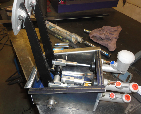
Everything seems to fit and function correctly for now so I am happy with that. I got out the TIG to make some “pretty” welds on the pedal box seams. I figure folks might see it as it seems to be hanging down in every low angle shot I see of these cars. Besides I had not used it in a long while so good for practice too.
I fit it back in the chassis and after double checking my measurements I went ahead and put some welds to it. With all the bits back in the box it looks good to me and another part I can check off that big to do list! 
I then added the lower tubes to the front bumper mounts and the cross piece / rad support for now. This will give me a good idea how things are lining up next time I test fit the body shell.
So then....
As I mentioned before I know there is going to be a bit of cosmetic surgery required on the body around the cockpit area. I think the overall shape is good but some alterations seem to have been made in the cockpit area. 
To be more specific it looks like the door openings have been lengthened by moving the forward part of the opening and therefore the cowl / dash area forward a bit, at least that’s what some comparison measurements indicate.
This also leads me back to believing the body is from Johnex and originally taken from an 80's Aurora. None of this would be a problem as it looks fine until you fit up one of the side curtains for the top or want to have the dashboard in the correct relationship to the cowl hoop. It also impacts the door hinge brackets. 
So having to consider that I have made some decisions again…. I am just going to scrap the whole thing 
Na, just kidding around 
I have known about this issue for a while now but was contemplating how to proceed. I had already decided that I would fit the body to the chassis and correct this issue best as I can.
I think it can be accomplished with one long cut and move the whole section back but until I have the appropriate structures in place like the door hinge mounts and dash mounts I won’t know for sure, it might be a couple of adjustments.
What I really decided is I am going to move forward with the metal parts and build what I have heard others refer to as the “go kart” stage and then worry about the body.
So I want to build this up to working suspension, rear axles, differential, driveshaft, transmission and engine. The brake and clutch systems, the fuel tank and lines, The cooling and exhaust system, and some of the basic interior layout like seats and mounts and the foot boxes and trunk pan.
I think in the end this will be much easier and should deal with all the brackets, clips and tabs that hold all this stuff and far easier to access these areas without the body in the way. Then that stuff can all come apart again and I will move onto the body issues.
To be honest a big part of me wanted to get on with the body part as it always feels like you have accomplished more when big pieces start going together but I believe all the little tabs and brackets will really frustrate me in the end.
This way I will be fairly confident that it will all go back together smoothly
……Famous last words……… 
Also I have also taken some time off from the build , don’t panic I am not stopping for any longer than I need to. I just need to get some other around the home projects out of the way that have been backing up and I am quite frankly feeling guilty about.
I am however still actively acquiring parts for this new plan, I already have a bunch but there is still a bunch to go. Some big Like a windshield , seats and bumpers and some smaller like the rad, gauges and lights but it all adds up and I need it all in the end. What it really means is I might not have any real progress updates for a month or so other than “ hey look at what I found” posts.
Speaking of "hey look what I found", it is really something that I recently found out about Ford or at least my engine.
If you have noticed in some of my pictures with the engine in place the block is rusty brown….I always wondered about this off and on as it never really added up.
The fellow I bought it from had it stored indoors, apparently it has low miles, the compression is good, the oil pressure is good. Everything I have taken apart is easy enough, there seem to be few oil seepages but how did it get so rusty?
I thought perhaps the previous owner power washed it clean or something but upon closer inspection no, there is still oil and dirt from valve cover seepages and oil filter spills, the original oil pan is still mostly black too.
I had at one point suspected that it had sat in a field and corroded over time but the oil pan should be really bad in that case.
I got curious recently and cleaned some of the oil and dirt from below the valve cover and there is nothing under it other than cast iron, hmmmmm
A quick Google search gave me some answers on a couple of Mustang forums where fellows are asking about original engine block colours. It seems in the later 80’s and in to the early 90’s the correct factory V8 engine paint color is NONE!
For some unknown reason Ford did not paint the engine block assemblies in most Mustangs then, the oil pan and valve covers would be black but nothing on the block, and yes within a couple of seasons they just rusted.
If you bought a new or reconditioned engine they would be painted black or grey but not on the production line, so mystery solved I guess.
I suspect this was something dreamed up by the accounting department but who knows, what know is mine will be painted black after I clean it and put it back together with a bunch of new stuff, no rusty block for this kid!
So, on that bombshell,
That’s it for now, I will report back as soon as I can. Till then the parts hunt continues and I hope I can get this chassis rolling on the floor sooner rather than later.
Stay happy my friends,
Hudson
.
__________________
Yes, I know,....... but it's mine you see..... 
Perhaps he was always a shyster, but we just chose to over look it for awhile.
You build what you like and I will build what I like...it's all good 
You know that guy,
The one in the neighborhood who likes to hang around the garage while you are working and talk about back when he had that killer 1977 Chevy Mustang
Last edited by old willy; 06-15-2022 at 07:15 PM..
|
05-16-2022, 06:15 PM
|
 |
CC Member
|
|
|
Join Date: Aug 2013
Location: Canandaigua,
NY
Cobra Make, Engine: SPF MKII Riverside Racer FIA
Posts: 2,507
|
|
Not Ranked
Hudson,
I will get you the quote on the shipping for the windshield next week, been busy planting a new vineyard and should have time next week to finish packaging the windshield and taking it to UPS for a quote. I would suggest that you start figuring out what you want to do for a fuel cell/gas tank as you will need to figure out where to place it.
Jim
__________________

|
05-16-2022, 10:34 PM
|
 |
CC Member
|
|
|
Join Date: May 2021
Cobra Make, Engine:
Posts: 528
|
|
Not Ranked
Every time I look at your project, the only word I can think of is, gobsmacked! Cheers, Dennis
|
05-19-2022, 07:46 PM
|
|
CC Member
|
|
|
Join Date: Oct 2017
Location: Baysville,
Ont
Cobra Make, Engine: Mine, small block FORD
Posts: 360
|
|
Not Ranked
Hey Dennis!
Thanks so much for the kind words, it is the type of encouragement that helps keep me going sometimes.
There are so many amazing builds on here and I have learned so much and borrowed images and ideas I just want to post mine to give back to the community that is helping me. Perhaps I have nothing new to add to the knowledge base here but I want to do my part to help keep it going. Perhaps even inspire someone else that they can do this crazy thing too
Jim,
Thanks for the update and I am glad to hear your busy planting, there is only one good season to get it done so good luck. I will watch for your message about the shipping but don't stop planting season on my account OK. I can wait.
Cheers folks!
Hudson
__________________
Yes, I know,....... but it's mine you see.....
Perhaps he was always a shyster, but we just chose to over look it for awhile.
You build what you like and I will build what I like...it's all good
You know that guy,
The one in the neighborhood who likes to hang around the garage while you are working and talk about back when he had that killer 1977 Chevy Mustang
|
05-25-2022, 03:16 PM
|
|
CC Member
|
|
|
Join Date: Aug 2013
Location: Canandaigua,
NY
Cobra Make, Engine: SPF MKII Riverside Racer FIA
Posts: 2,507
|
|
Not Ranked
Willy,
I sent you a message regarding shipping. Let me know if you received it. It does to show up in my sent folder.
Jim
__________________
|
08-07-2023, 02:50 PM
|
|
CC Member
|
|
|
Join Date: Oct 2017
Location: Baysville,
Ont
Cobra Make, Engine: Mine, small block FORD
Posts: 360
|
|
Not Ranked
OMG has it been that long!
A long, long, long, long, very long, overdue update
.
Well hello again everybody!
I cant count how many times I have sat down to down give you all an update over the past months, but just never seem to get finished.
I also think I am back to that issue of fighting between spending my time actually working on the car or sitting here telling you what I have been up to again. I will do my best to get caught up here and make this a more regular thing as working on the car has become a more regular thing again.
I know said I was taking an extended break to get some other projects out of the way
and I did. However things never go quite the way you think they will and things always take longer than you think they will
.hmmm.
Some of the things were planned, such as the stone work and windows on the house that honestly had been put off from the previous years, but other things just sort of came up. Also honestly I did throw a couple of things in my way to force me to get them done too and I did get some of it cleared away. Plus the regular stuff of life, working, family matters, friends,
C'est juste la vie
.
Then there is the strange issue that perhaps you too have also encountered, that is, when I am really focused on a large project and get pulled away from it for a time I tend to have a hard time getting my head back into it again. 
Its strange, I want to get it done but my mind has wandered and I need to almost force myself back to working at it, its just strange. Perhaps it is because I have other hobbies as well and I feel the pull to do them too or?? I just dont know.
So I have been working on the roadster again, slowly for a while now but , sorry, I just havent gotten around to writing and posting about it.
There have also been some issues with the project but more on that later.
On the good side of the ledger I did get some parts ordering done over the summer, fall, winter, spring. A windshield assembly from Shell Valley arrived way back last summer, a wonderful birthday present ( well I hope its wonderful ).
I then ordered a beautiful set of Smiths gauges from Nisonger Instruments in NY state, they were great to deal with and very beautiful stuff too.
Yes I know, I know, most of the 289 cars had Stewart Warner, but the early ones, the European ones and then the 427s had Smiths and because this is my car thats what I want. I just like the look of them better. No offence to anyone but I have always found the classic Stewarts look fairly industrial by comparison.
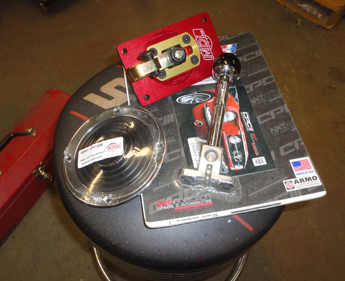
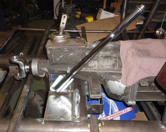
I put in a small order to Modern Driveline for shifter stuff and also picked up a handbrake handle that I think with a small modification will work nicely.
There were other odds and ends too but more on them later.
So I will try and get back on track here with my reporting and try and get caught up while I try and keep moving forward, so then on to the good the bad and the ugly.
So getting back to it
.
I started sort of right where I left off, the differential mounting. My urethane front mounts arrived after about 3 months! Bloody covid delays
So
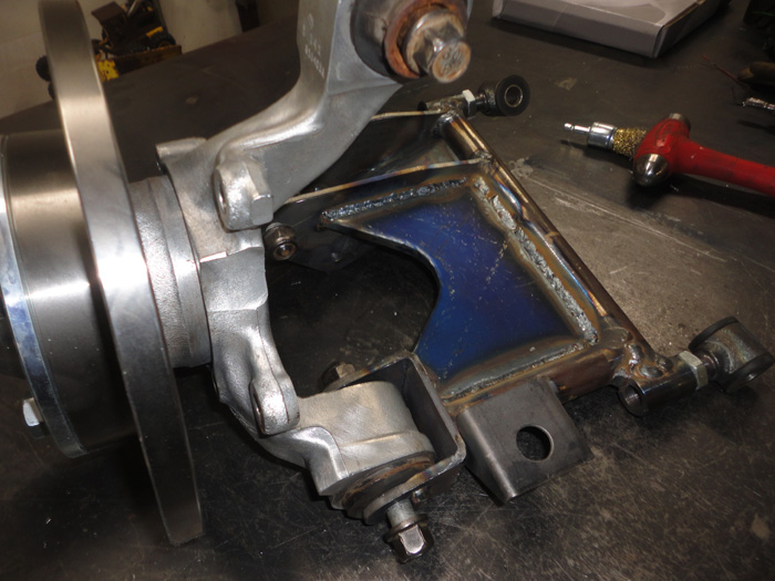
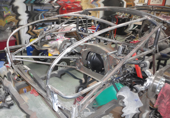
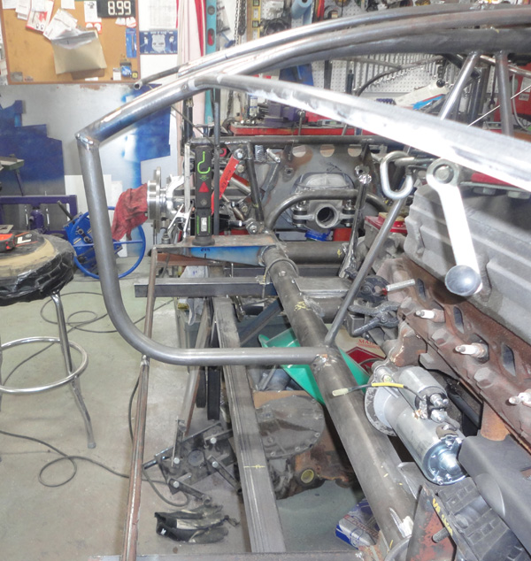
I needed to pull the diff case back out to deal with the new mounts, the rear cover and the fact its just an empty shell! Well it was then I found out I really couldnt remove it, not without removing the front mounts completely and twisting it in a bizarre way and I also realized the when it is fully assembled with a rear cover on, that would just be impossible. There is a picture in my last post where you can see them, kind of ugly really.
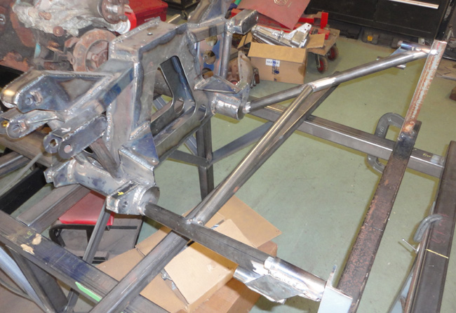
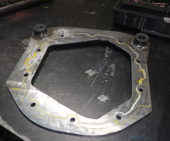
So really a bad way to start back at it but back to the drawing board, the diff obviously needed to mount from the top as it does in the T- bird, etc. so it can drop straight down and out. I did some measuring and figured I could find enough space at the rear of the tunnel to add a compact upper mount design and I had just enough 1 ½ DOM tube in the shop to make it. It certainly doesnt look like anything the original chassis had but it is above the main tubes and hidden behind the rear cockpit panels so no one will really see it.
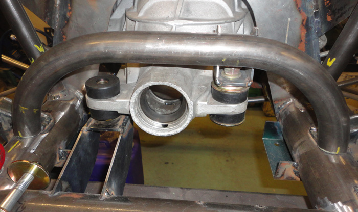
This picture does have one of the first attempt mount pieces on the left just holding the diff while I fit up the new top mounting point, they were fairly ugly, just flat pieces with a plate on top, simple to make but did not work, I think the new one is much more elegant 
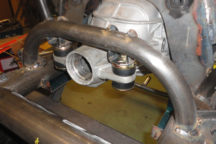
It seems to work well, I should be able to build up the differential and lift it into place with the floor jack easily enough. Also it currently looks like the old school steel cover is the winner for fitting, I might still cut and try one of the alloy ones, but more later. The steel one will need a couple of plug holes added but thats not a big deal.
So problem solved, I hope
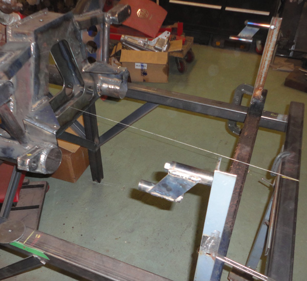
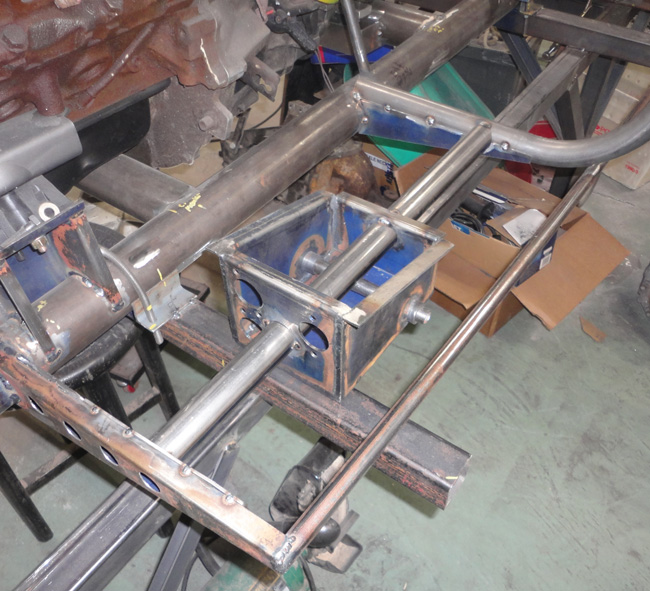
Then as I wanted to start working on the interior aspects of this car I made up the brake handle bracket and tacked it in place relative to the transmission cross member but remembering that I had moved it rearward 1 ¾ inches. We will see how it lies up with other things as I build the floor and tunnel but for now there it is.
I wanted to get the suspension back on for a body fit up at some point soon, as I had some new thoughts about how things might be lining up around the cockpit area.
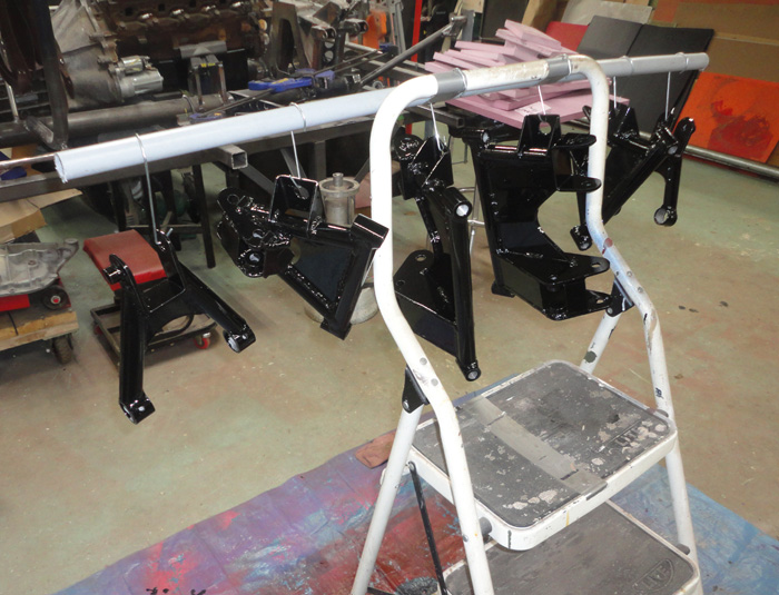
I got the parts out of storage and decided to add the gusset to the lower rear arms. I was still not sure what the rear axles were going to be but was still thinking they would be shortened Ford ones so I need to clear the CV boots. A piece of 14 gauge with a formed lip to stiffen it should work nicely. Then the whole lot was sand blasted and painted with Por15. 2 coats with a brush, very nice.
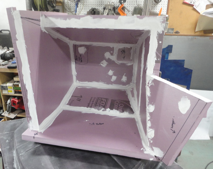
Next I wanted to make the foot boxes and trunk liner fiberglass parts; it was getting later into the fall and before the weather got too cold for stinky fiberglass work outside I thought I had better get a move on.
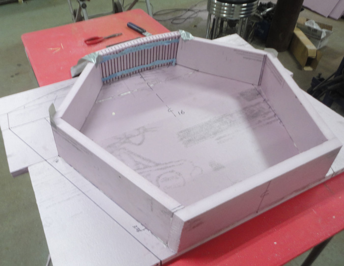
I had received a copy of Chucks newest drawings and with some previous experience making fiberglass moulds I got to work. As I only want to make one copy of these and keep my cost down I decided to go with builders foam from my local construction store and my favorite polyurethane glue. I have used these products before to make mould plugs so it should be fine for a one time mould.
The trunk liner and boxes are mostly comprised of flat surfaces so it should be a case of cutting out the various panel shapes and bonding them together and for the most part it went like that.
The trunk liner does have a curved panel at the back and the tapered stiffeners in the bottom but it was just a case of making a flexible piece for the rear and cutting the bevels on the stiffeners with the table saw and then tapering them down to shape with a sanding block.
This is one of the best things about using this foam, it cuts and sands fairly cleanly. For filleting the corners and filling minor imperfections I just use regular drywall compound, again, cheap and sands easy too.
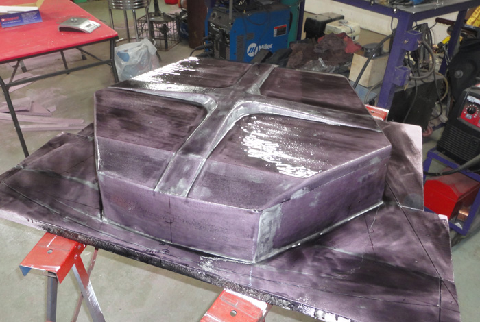
The downsides of this method are also related to the foam board, it is very easy to damage the surface, you can scratch it with your fingernail so care is a must. The major issue however is the fiberglass part; the polyester gelcoat and the resin will MELT THE FOAM! I have seen others use latex paint as a barrier coat with varying degrees of success but my preferred product is West System epoxy for coating the final shape, just apply a thin layer and when it cures depending on the surface finish you want, wet sand it and wax it up good.
Things were going good or so I thought
..
I started with the trunk liner, really it is just like making a regular mould plug, its a positive shape just a case of getting the sizes and draft angles right. I did have a bit of head scratching about the angle of the drop towards the trunk opening as what is on drawing doesnt really make sense but I took some measurements from my setup, then a good guess and made some minor changes I saw fit.
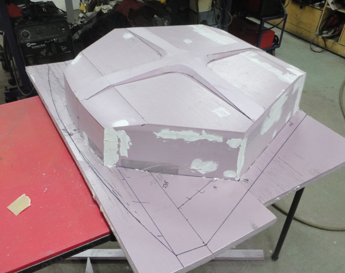
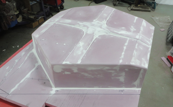
I got a coat of epoxy on it and I will double check things again but I wanted to get started on the foot boxes.
With plan in hand I started measuring and making shapes. The drivers side went together surprisingly well and there is only one panel that really isnt flat so I thinned the foam and flexed it to shape.
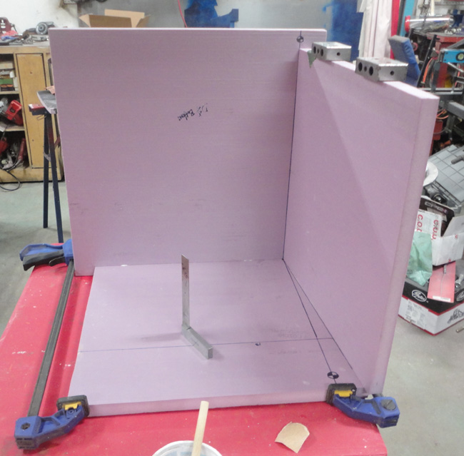
Its really great stuff to work with, you just glue it and pin it with toothpicks, if you need too you can clamp or tape things for a couple of hours till the glue sets up enough to handle it.
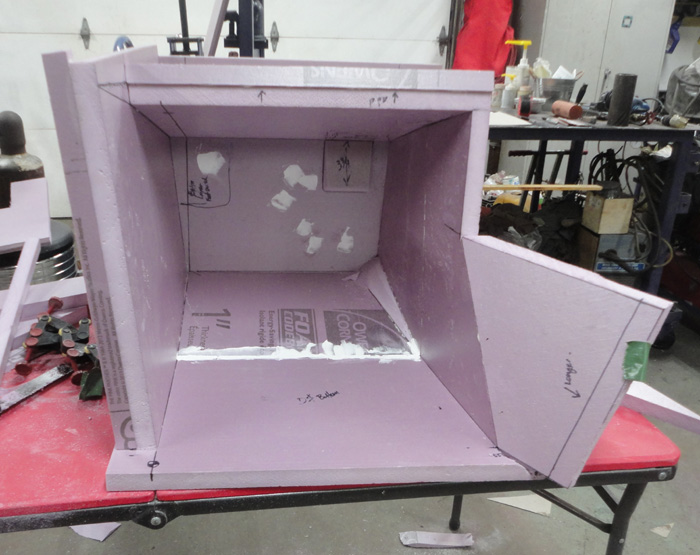
When I got to the filling and sanding stage I started to work on the passengers side box, again I measured and cut the shapes, but well into making it I had a thought or two about how things were lining up, the passenger foot box seemed to be a bit longer than the drivers and I know that the battery tray mounts to the front and it is supported from the front outrigger, so how was that going to work out?
I took a measurement and it looked promising, perhaps ½ inch short but I could allow for that in the battery tray and bracket.
So, Ok, but something was still bugging me
. that got me thinking about the drivers side, I did not check anything over there and I had noted in my head it is a different length. I got my ruler and well, something was just not right at all!
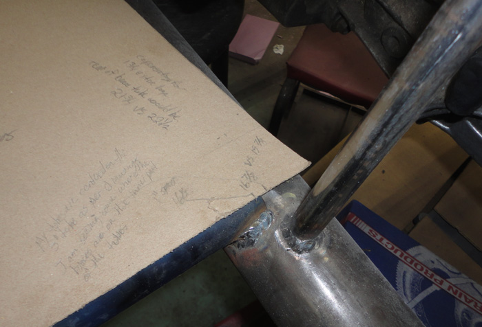
I made a full size cardboard template of the bottom of the foot box and checked that in place.
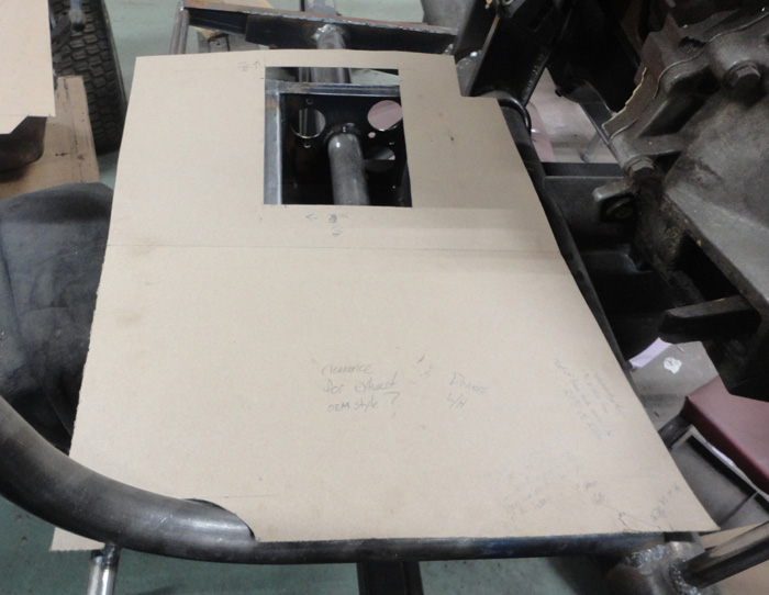
Even more things looked wrong! WTF? I started rechecking all the appropriate measurements, everything, even the spacing of the main chassis tubes although I knew they were not wrong, I surely would have noticed that by now. But currently the box seems way to long and way too wide
.?
So a message was sent, telling what I found and asking if there is a discrepancy in the foot box measurements. Were these taken from another replica perhaps? And we started comparing notes
Hmmmm
I must say Chuck was great about getting back to me, he doubled checked some of the measurements and was honest about the fact the chassis drawings have the pedal box located about 1 ½ inches to far aft and a bit too close to the main tube as well, another unrelated discrepancy I noticed with the rear framework was also confirmed but I had used the correct measurement so no rework is required there. Chuck has also corrected the drawings and sent me the updates. If you have a digital set of his drawings in your collection I am sure he will send you the update if he hasnt already.
He says his measurements were taken from a battered original set of boxes he has, and a reproduction set he had access to and are the same as the ones used in his build.
So if those measurements are correct and we have established that the pedal box is currently in the wrong place why is the rear part of the foot box still about 1 ½ inches too wide and why is it the same on both sides? Is it me? Did I forget how to measure?
Much more re-measuring to follow
I have condensed a lot of the back and forth on this and the time to tell it takes far less time than it took to check, check and recheck stuff. Not to mention the frustration of finding out stuff you have been doing is going to need to be re-done 
. Nobody likes that news, but fear not fellow travelers, things are going to work out in the end.
I will check back in again soon.
Cheers,
Hudson
.
__________________
Yes, I know,....... but it's mine you see.....
Perhaps he was always a shyster, but we just chose to over look it for awhile.
You build what you like and I will build what I like...it's all good
You know that guy,
The one in the neighborhood who likes to hang around the garage while you are working and talk about back when he had that killer 1977 Chevy Mustang
Last edited by old willy; 09-20-2023 at 11:07 AM..
|
08-21-2023, 07:27 PM
|
|
CC Member
|
|
|
Join Date: Oct 2017
Location: Baysville,
Ont
Cobra Make, Engine: Mine, small block FORD
Posts: 360
|
|
Not Ranked
One step forward, two steps back......pt1
Hello again friends,
So still moving forward with the build and still trying to catch up with my posts, here we go again.
This is going to be a bit of a long one, as it took me awhile to get to this point.
I am sure I will miss some things as some of this happened a few months ago and I am working with few notes, mostly memory and the pictures I was taking.
After discovering the discrepancies with the foot boxes and the chassis and having no real answers that were obvious I had to stop and think for a bit, honestly I was fairly bummed out by the whole situation, the drawings were supposed to make things better but here I am contemplating cutting up one part or the other to make things fit.
The real question was which one?
My beautiful bride could see that this was weighing on me and after talking it out for a bit she asked me something like what would you be doing if you didnt have the drawings? So of course the answers was, I would be making it work to the best of my abilities and using the parts I already have.
I am just so lucky to have her
..
So back to the drawing board, I accepted something was going to need to be redone so lets see what we have
..
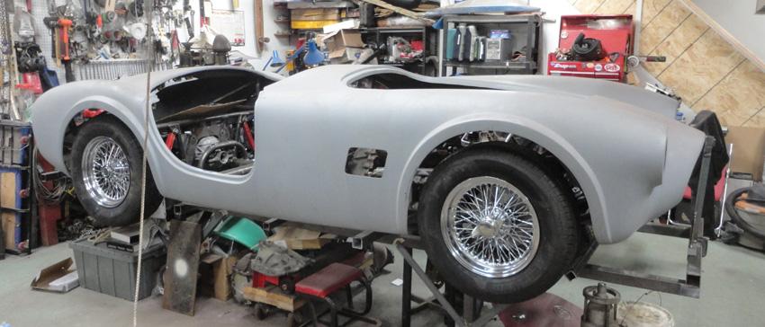
The body needed to go back on for another fit, what would be the path of least resistance I guess.
So suspension back on the chassis
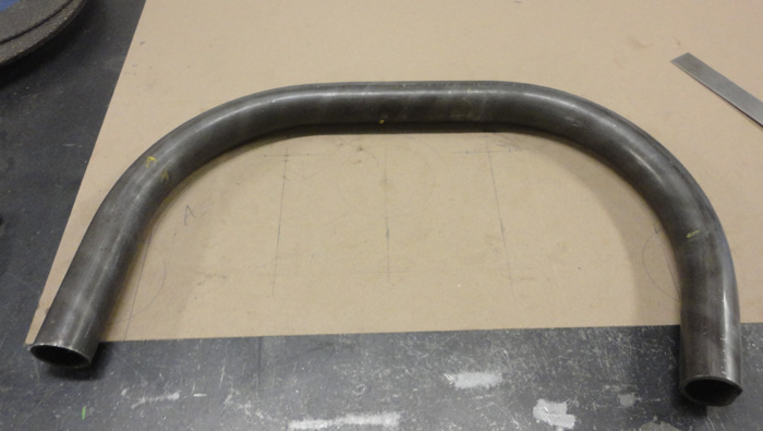
I also thought I should check some other points so I fabbed up the tube that would support the front of the body at the hood opening and made a temporary support stand to hold it at what I assume was the correct height according to the drawings.
I figured this was an important dimension for the later radiator installation.
It was also a bit of a chore to get the body back on now that I had made the front bumper mounts and some of the rear tubing that resulted in my needing to cut the lower rear part of the body off. I will reattach it when I do the final body work.
So with the body back on and the wheels in place I set to figuring.

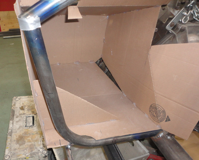
I made some cardboard templates of the door hinge brackets, one to drawing one modified a bit to suit the current cowl tube angle vs the current body side angle.
I decided that I would change my plan to fix the door opening size issue and front cockpit tube issue in a different way.
By moving the body rearward about an inch to make the door hinge bracket sit where it should in regards to the front of the door opening, the front cockpit tube is also much closer to the drawing size given and should work fine in the end.
So I think the only cut and move operation will now be in rear area, bringing the rear section forward as I correct the door size and allowing the required space between the tubing if I want to add the roll bar ( not sure) also the storage pocket behind the seats should also be the correct size now.
From the side with the wheels on it still looks fine too, so I am happy.
The rework for this change is the rear square tube that supports the trunk liner and the rear of the body. I did not want to remake the rear frame tubes so I added a 1 inch spacer tube and reattached the support tube to it. Hmmmm.
Late last summer a FFR roadster appeared in the town I work in, I sort of know the fellow in passing but had no idea he was building one. Honestly very few people around here know I am building anything either. It was still in red gel coat and filler but cool to see it out. I saw it again just last week and now it is gunmetal grey with black stripes, looks very nice.
One thing I did notice however was his licence plate. There was not enough space between the light and the trunk handle resulting in a notch cut in the plate to accommodate the handle. I want to avoid this ( I am sure he was not pleased about it either ) so I dug out my trunk lid and handle and did some checking.
Glad I did too. I needed to lower the handle position a bit and adjust the rear support tube down a bit trying to factor in the trunk lid frame tube and handle mount as I plan on just using the skin of the trunk bonded to a more correct looking tube frame.
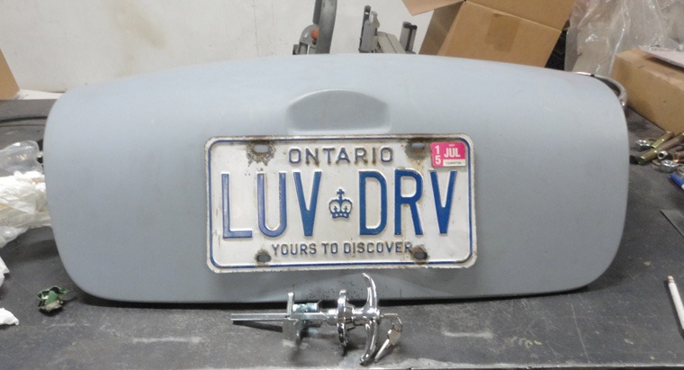
Yes the licence plates will need a restore as they have been with me since 1989, I have always tried to have them on something interesting. The last thing was a pearl lime green Jeep Rubicon, but I think the 289 will be their final home.
But back to the body
.
So what I needed to know was do I pull the lower part of the body in to match the cowl tube shape and rework the footboxes or rework the cowl tube to suit the body and footboxes?
With the help of my wife we positioned the windshield as close as we could to the correct angle and then I pulled the lower part of the body in with a ratchet strap to check. It seems that when I pulled the body in to work with the cowl tube the curve on the top of the body became too extreme for the windshield. Sure I could try and clamp things so the upper would not change too much but I think I would be fighting cracks all the time so the decision was made to rework the lower parts of the cowl tube .
Right or wrong it fits my body better, so that is what I will do.
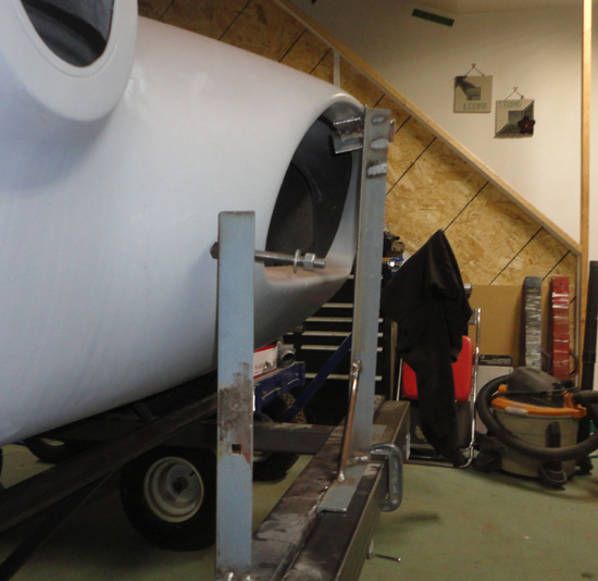
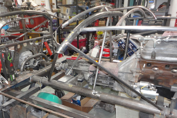
I also decided that while the body was back on I would add more of the inner body structure and check some other things.
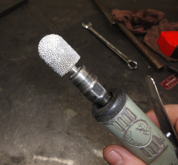
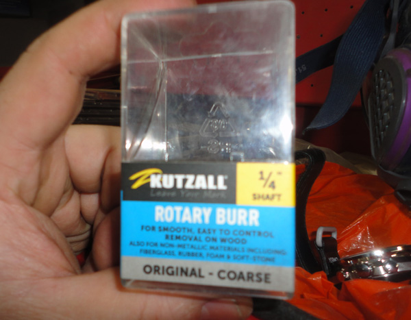
I bought one of these ¾ inch diameter rotary burrs to run along the areas where the body meets the tubing, it does a nice neat job of it, I highly recommend it
I added the framing around the trunk area first, wow those side tubes are had to form, just the way the radius changes from the easy curve of the top section to a fairly tight curve at the rear really had me scratching my head.
I got it in the end but some of it is a tad rough, fortunately most of it wont be seen in the end. I will need to come up with a much better way of forming the tubes around the doors and other areas.
I think my old friend "Cerrobend" will be needed
The tubes around the hood went much better with their longer curves that I could just roll until they fit the body.
I must say adding those simple structures certainly stiffens the body.
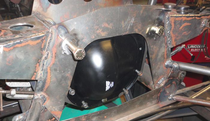
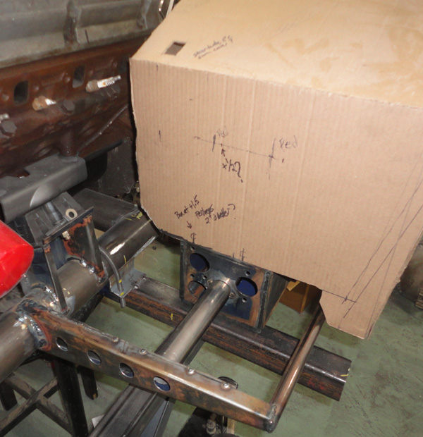
I also decided to check on the bumper mounts in the front.
Using the height jig I built them with I discovered they were a bit on the low side for my body so they were adjusted upwards with a couple of strategic cuts, much better in the end I think.
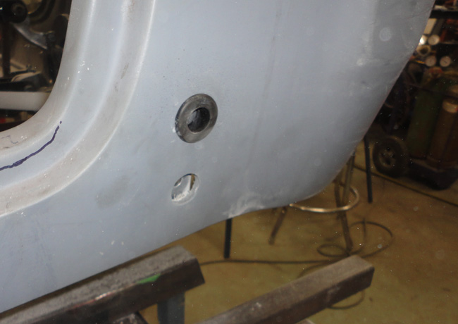
Using the mounts and a sharpened piece of rod in my drill I made 3/8 holes through the nose then with a homemade cutter centered in the bumper mount again I made the oblong holes to take the grommets.
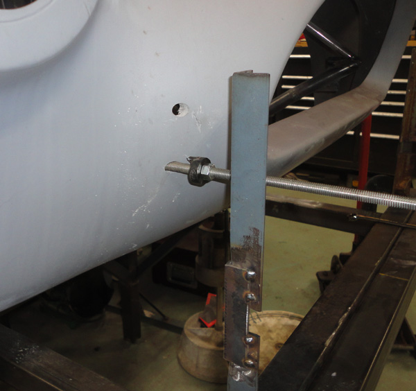
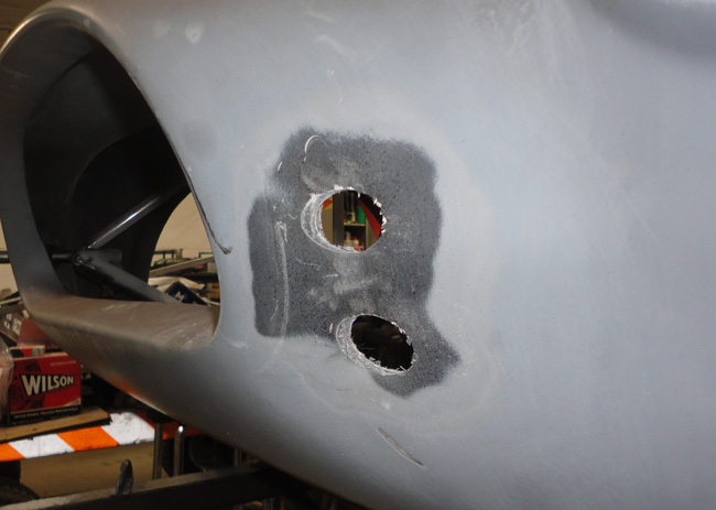
Everything seems to fit fine and looks good so I will check that off my to do list
I then made the rear bumper mounts checked the fit and tacked them in place and using the same homebrew cutter I did the rear grommet holes too
.check
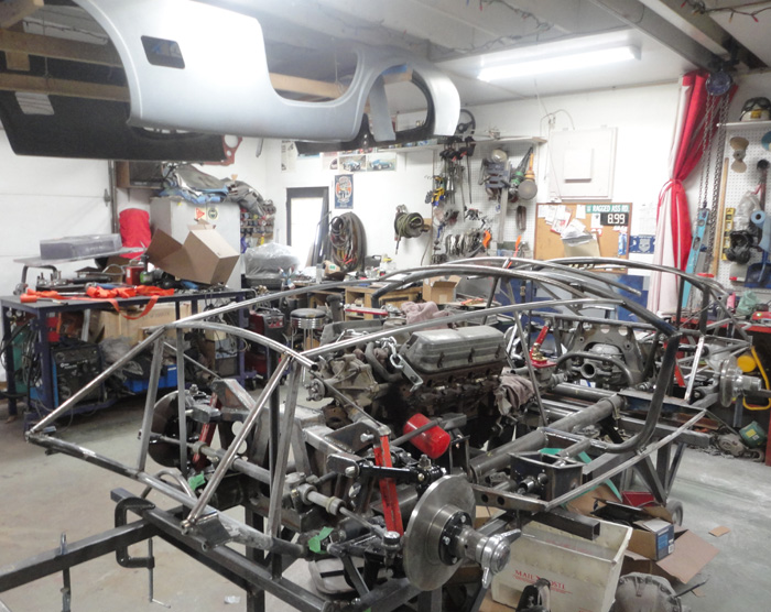
So with that all done the body when back up to the ceiling and I moved onto the larger metalwork .
Stay tuned, it only gets better
1
__________________
Yes, I know,....... but it's mine you see.....
Perhaps he was always a shyster, but we just chose to over look it for awhile.
You build what you like and I will build what I like...it's all good
You know that guy,
The one in the neighborhood who likes to hang around the garage while you are working and talk about back when he had that killer 1977 Chevy Mustang
Last edited by old willy; 09-20-2023 at 11:17 AM..
|
08-22-2023, 03:57 AM
|
|
CC Member
|
|
|
Join Date: Aug 2013
Location: Canandaigua,
NY
Cobra Make, Engine: SPF MKII Riverside Racer FIA
Posts: 2,507
|
|
Not Ranked
It's moving along Hudson. I like the way that you approach things and how you are able to re-adjust when plans need to change. Keep plugging away and you will get there.
Jim
__________________
|
08-23-2023, 09:29 PM
|
|
CC Member
|
|
|
Join Date: Feb 2003
Location: Plymouth,
MA
Cobra Make, Engine: MidStates, 351C, 4spd, 9"
Posts: 405
|
|
Not Ranked
I have footboxes, trunk trays, and chassis drawings. Reach out if you want to compare notes. Your footbox outer sides should rivet to the cowl tube before their flange, so there is something wacky with all that space in between. Way to keep moving forward. Your foam plugs are nice work!
__________________
"It's not about getting from point A to point B. It is the point"
-J. James
M. Krause
1.508.944.3368
|
09-04-2023, 06:49 PM
|
|
CC Member
|
|
|
Join Date: Oct 2017
Location: Baysville,
Ont
Cobra Make, Engine: Mine, small block FORD
Posts: 360
|
|
Not Ranked
Hi there,
Thanks for the offer, I may need to ask a question or two.
I really don't completely understand where the issue is but there certainly was one. As I mentioned before, I just need to proceed and make this work with what I have on hand, so long as it looks good in the end.
I have no other 289 cars to compare anything with so perhaps some of the issues have more to do with my body.
I am fairly certain it is a Johnex body and was modified from a mold taken from an 80's Aurora that was apparently molded from an early 260 body so that is a lot of room for error.
But as for the foot box being too wide for the chassis, both being built from drawings from the same source I have no idea what's up there, I have my theory's and suspicions but until I talk it over with the provider I am reserving judgement.
.
__________________
Yes, I know,....... but it's mine you see.....
Perhaps he was always a shyster, but we just chose to over look it for awhile.
You build what you like and I will build what I like...it's all good
You know that guy,
The one in the neighborhood who likes to hang around the garage while you are working and talk about back when he had that killer 1977 Chevy Mustang
Last edited by old willy; 09-12-2023 at 06:30 AM..
|
09-04-2023, 07:03 PM
|
|
CC Member
|
|
|
Join Date: Oct 2017
Location: Baysville,
Ont
Cobra Make, Engine: Mine, small block FORD
Posts: 360
|
|
Not Ranked
one step forward....part deux
Just a quickie, wink, wink, nudge, nudge……. 
Alright time for part 2 of one step forward two steps back.
I would say there may also be steps to the side and…….. Ok I don’t know what it all means either, I hate redoing things but it was bound to happen and I am sure it may happen again before this is over.
I think I have some real trust issues now, and I find myself rechecking a lot of things, but moving on…..
With the body back off I am left with some major reworking but also some nice new frame work I can finish weld and such.
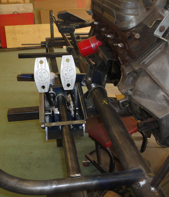
I then turned my attention to the pedal box issue. I cut the old mounting free and jigged it up a bit so I could move things around and check the location until I was happier with things. I so wished I had not finished welded this area, I figured it was all correct based on the drawings but…….. Oh, well
I believe I mentioned before there was an error of about 1 ½ inches fore and aft and a bit side to side too. I ended up moving it forward the 1 ½ inches and settled on moving it out 1 ½ inches too, it is a bit more than Chuck said it was out but I liked the idea of a bit more room between the gas and brake pedals.
So knowing those measurements I went ahead and braced the cowl tube with some angle iron and cut out the lower section, arrrrggghhh!
I set up my old 105 bender again and using a new drawing bent new lower sections to fit it.
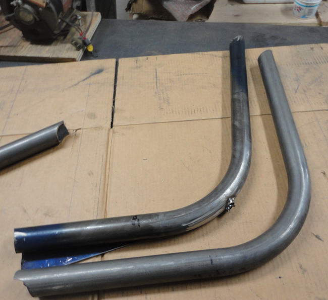
I also needed to make new lower gussets and increased their length by 1 ½ inches as well. I welded it all in and braced, cut and replaced the driver’s side too.
This time with the pedal box in what I hope is the correct location.
Time to recheck the fit with my cardboard footbox mock up.
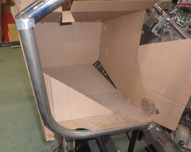
Looks much better now , I guess I am happy?? with that, however it still would have been better not to do it at all but….
Now I need to move on to something else but what?
I wanted to deal with the floor supports but they need to fit the seat rails and without the seats in hand (that’s another story) so I really don’t want to commit to a location yet.
That’s OK, I have lots of other things to keep me busy so I will move on to some of those…….
Till next time, have fun, enjoy the sun,
Hudson
.
__________________
Yes, I know,....... but it's mine you see.....
Perhaps he was always a shyster, but we just chose to over look it for awhile.
You build what you like and I will build what I like...it's all good
You know that guy,
The one in the neighborhood who likes to hang around the garage while you are working and talk about back when he had that killer 1977 Chevy Mustang
Last edited by old willy; 09-20-2023 at 11:19 AM..
|
09-04-2023, 07:36 PM
|
|
CC Member
|
|
|
Join Date: Jul 2003
Cobra Make, Engine: Unique Motorcars 289 USRRC, 1964 289 stroked to 331, toploader
Posts: 1,135
|
|
Not Ranked
 Wow!
Wow!
Good progress!
__________________
Paul
Unique Motorcars 289 USRRC
1964 289 5-bolt block
Toploader and 3.31 rear
|
09-05-2023, 04:47 AM
|
 |
CC Member
|
|
|
Join Date: Feb 2001
Location: Leechburgastain,
PA
Cobra Make, Engine: Myself/Body from CSX-2575 & hand built Birdcage
Posts: 676
|
|
Not Ranked
Looking great! On the 8.8 real axles, I'm using a Explorer alum 8.8 I don't want to use CV axles I went a different direction I machined down the inner & outer dive stubs cups to a flat with a register & used the 8.8 pinion flange machined to except the flat & register drilled & tapped with grade 8 studs to accept a 4 bolt drive shaft U-joint flange. On the Inner stub same deal bolt on a pinion flange so now i can use a Spicer slip spline drive shaft I found a Jeep front diff drive shaft works perfect they can be cut to any length & have a slip spline. I'll post some pix later.
Pix. https://goo.gl/photos/898aU1K4dZxSTFq89
__________________
6S1941
Allied 289 Slab Side
73 2.3 turbo pinto
Last edited by map; 09-05-2023 at 09:00 AM..
|
09-06-2023, 11:22 AM
|
 |
CC Member
|
|
|
Join Date: Mar 2002
Location: Mooresville,
NC
Cobra Make, Engine: Factory Five chassis/Mr. Bruce slabside
Posts: 603
|
|
Not Ranked
Mike (MAP) an incredibly talented Man.
Mike, your skill set is just amazing, and thank you and the Brucester for my 289 body.
John O
__________________
jjo42
|
09-12-2023, 06:24 AM
|
|
CC Member
|
|
|
Join Date: Oct 2017
Location: Baysville,
Ont
Cobra Make, Engine: Mine, small block FORD
Posts: 360
|
|
Not Ranked
Hi Mike!
Great to hear from you again. The last time I checked in on you there was much work going on with your hard top.
I am playing some serious catch up with my posts. Most of the aforementioned figuring and reworking took place back in January/ February according to the picture dates.
Alas, you are jumping ahead in the story my friend
I believe there is an old saying something like..... Two great minds think a like...or is it... Fools seldom differ ? I can never remember
I had better get back to work here and get my next post......posted
.
__________________
Yes, I know,....... but it's mine you see.....
Perhaps he was always a shyster, but we just chose to over look it for awhile.
You build what you like and I will build what I like...it's all good
You know that guy,
The one in the neighborhood who likes to hang around the garage while you are working and talk about back when he had that killer 1977 Chevy Mustang
|
09-18-2023, 08:04 PM
|
|
CC Member
|
|
|
Join Date: Oct 2017
Location: Baysville,
Ont
Cobra Make, Engine: Mine, small block FORD
Posts: 360
|
|
Not Ranked
Pain in my rear...end
Hello again all,
So another catch up / update for you. A bit of a long one……..
After the cowl tube rework and pedal box fixes I wanted to keep moving forward. I wanted to deal with the floor but that means I need the seat rails and although I think I know what I am using there I really wanted the seats on hand to test the fit of everything and make decisions.
There are a lot of drawing notes from Chuck that go something like “ spacing to be determined by part used……” or something like that basically I need the parts to be sure they fit. So I ordered some seats and of course need to wait for them.
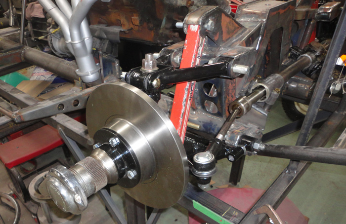
I still need to do everything else so what next, I turned my gaze to the rear end area.
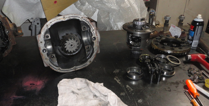
I have the diff mounts finished so what about the diff?
After my parts gathering and the kindness of friends I have four 8.8 differentials at hand, 3 IRS units and one straight axle with a trac-lok from the mustang that gave its engine and transmission for the build.
One of the IRS units is the alloy case currently in the chassis that had 2.73 gears and an open diff from a Lincoln, another one has an iron case, 3.08 gears and an open diff from the Cougar and the final one has the iron case, 2.73 gears and a trac-lok diff from a friend at work.
A nice collection of parts but what I want is the 3.08 with a trac-lok in IRS form. I am no expert on these things and don’t possess the fancy tools to check and shim these units but I had an idea….
So I started with the 2.73 trac-lok unit and took it apart, and cleaned it, keeping everything sorted out for later.
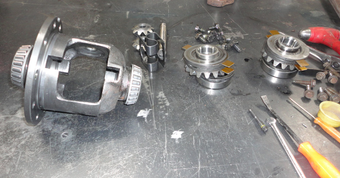
I discovered the friction packs were not worn out too badly but they were missing some of the tabs on the clutch plates so I need to fix that.
The best deal I found was actually an OEM Ford set on Amazon, go figure , and it was much cheaper than a budget Dorman branded set from a parts place…hmmmm…go figure that too.
These are obviously an upgrade as the tabs on the clutch plates are now rounded and there is a different stack up recommended with the plates and drive disks, the kit even included the Ford friction modifier for the oil, nice stuff!
So with the Trac-lok back together I disassembled the 3.08 IRS unit enough to remove the diff and its bearings and shims keeping track of everything’s location. I swapped the 3.08 ring onto the trac-lok diff and used the track-lok diff’s bearings and the shims from the 3.08 diff setup and bolted things back together.
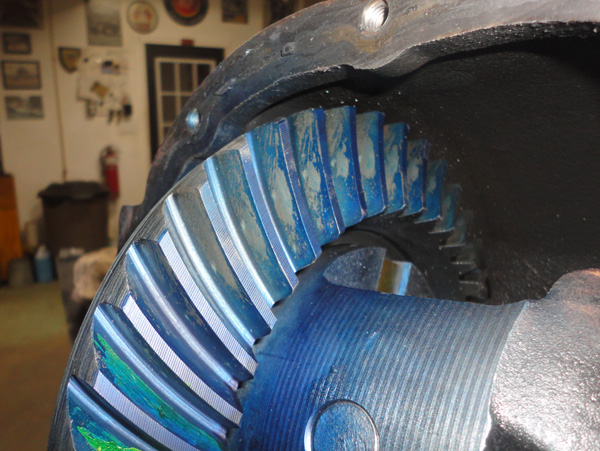
I put some layout blue on the ring and gave it a spin to check the pattern and used my dial indicator to check the backlash, I checked before I took things apart too.
You really need to love mass production and modern machining, the specs I have call for .008 to .012 backlash. When I checked the 3.08 set before I removed it, it was at .009, with the Trac-lok and its bearings in place of the open diff the backlash is now .010”, thanks Ford!
I am happy with that, I am not going to try and change it, it is within the range and the pattern looks good too.
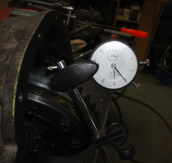 
I did not disturb the pinion in the case so that depth is still the same and it’s the same ring gear back in the same case too, so I think this might be a win 
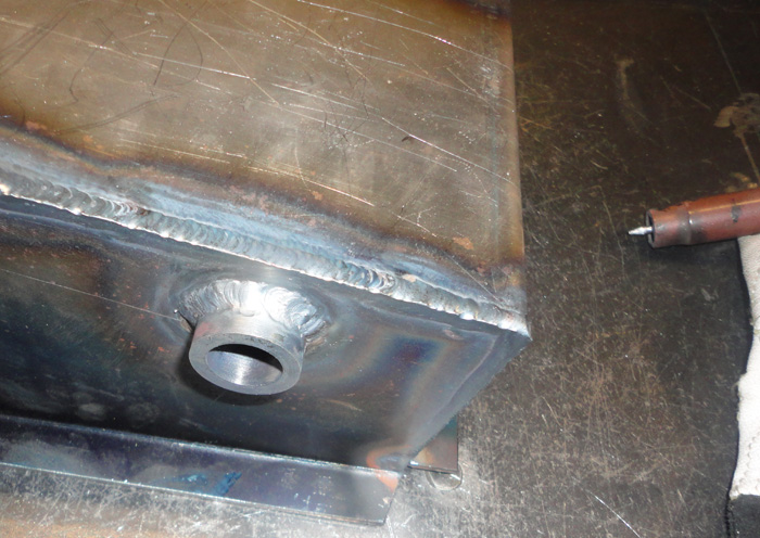
I also added a drain hole to the bottom of the case, threaded to use one of the OEM magnetic plugs I have.
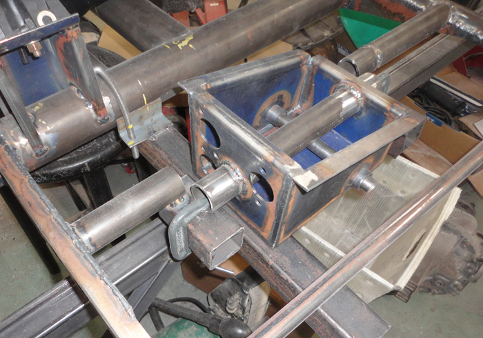
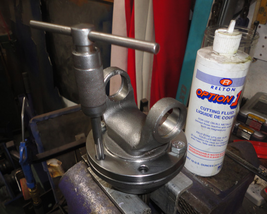
In the end it seems the steel cover is my best choice so I made a bung and welded it in the correct location for filling the diff, it also features one of those OEM magnetic plugs too.
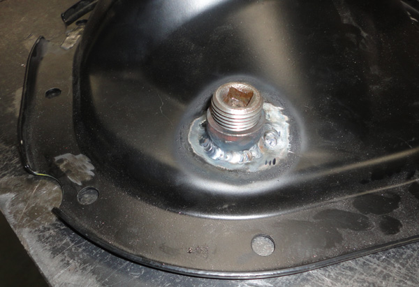
It was time to finish this up so I wanted to seal the mounting plate between the cover and the case, taking a cue from the factory alloy covers I ground a groove around the sealing area on both sides with a ( few) small diamond burr.
Then with everything super clean I applied orange adhesive sealant to both sides and torqued up the bolts. I painted the whole assembly with POR15 ( BTW it doesn’t stick to silicone ) and installed new seals and mounted it in the chassis. Fits perfectly and looks good to. Fingers crossed everything works in the end…..or rear end!
This all might be a bit long winded but I thought the explaining might help someone else down the road. I certainly spent a lot of time off and on worrying about how I was going to deal with the axles and such I just knew that at some point later I would need to.
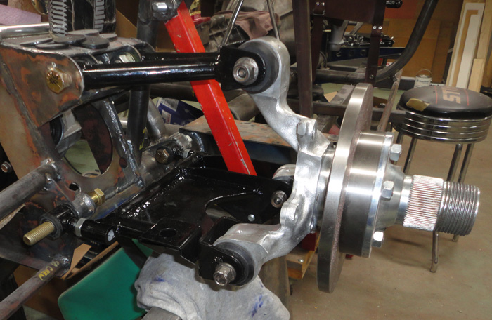
Now about those axles
After much reading, thinking and head scratching I had an idea, apparently not an original idea ( I see you Mr. MAP ) but at the time I thought it was, but really is anything an original idea anymore?.
I had measured the original Cougar subframe setup with the adapters and wheels before I took it all apart, then when I had the new design suspension in I measured it again. The stock CV / tripod axles would need to be about 6 inches shorter on each side . This did not leave much in the middle and a rather stumpy ugly end product.
I read horror stories of splined axles that had been shortened and re splined and then broke off, honestly most likely a case of too much power and poor/ no heat treating. I thought about doing an old school cut and shut with a sleeve or something, even just to get the correct length figured out so Mosher could make me some good ones later.
I found out someone was making 8.8 to Porsche 930 CV stub axles and got to thinking about making adapters of my own.
I found some posts on our site about the original Spicer(?) part numbers AC used and that got me looking at those parts. I had already picked up the yokes to build the driveshaft but there sure are a lot of different yokes, flanges and shafts available, wow!
I recognize the advantages of modern CV joints but the truth is even the mighty 427 Cobras and GT40’s had U joint, sliding spline type axles. Most Grand Prix cars of the 60’s did too, so if it was good enough for them….why not my car?
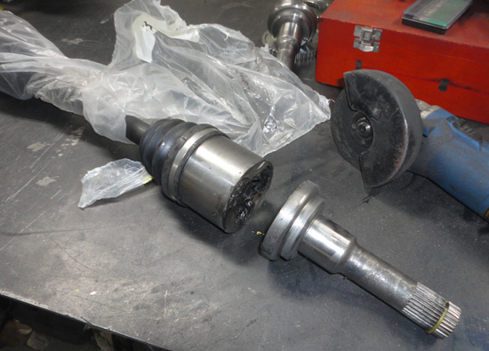
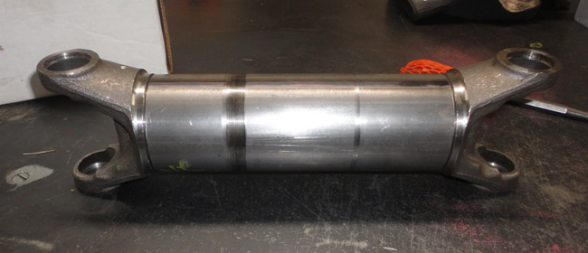
I took the old Cougar axles I had and sliced off the ends, lots of burning grease smoke and stink, but in the end a splined diff end with a retaining ring and a splined end with a nut for the hub.
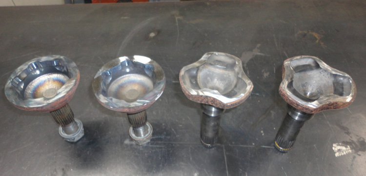
I thought about welding a plate to the inner and machining that for a flange but after I got to measuring and looking at the weld yokes for my drive shaft I figured I could machine the stub to fit a weld yoke and just skip the bolt on yoke part.
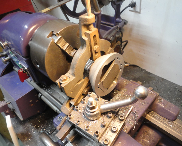
So I tried it out with my classic 1941 Logan lathe, the splined end will not fit in to the headstock all the way. This is the major short coming of the old Logan, the spindle hole is only just over ¾ inch but there are other ways to get this done. I cut off the excess material with a cut off wheel and I have a steady rest for the lathe so I used this to support the stub on the bearing / seal area with the stub as far into the chuck as I could. I just made light cuts and things seemed to go Ok.
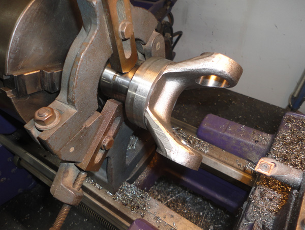
For the out board end I set the stub up the same way and tried to face cut it, wow that’s some hard stuff , honestly I had suspected the CV joint would be hardened for wear resistance. So I annealed them by standing the hub in a pail of water up to the body of the CV to avoid to much heat transferring to the spline area just in case. Then heating the top surface to a nice orange/red color and just letting it cool slowly. Back into the lathe and yes now it can be machined a bit more easily.
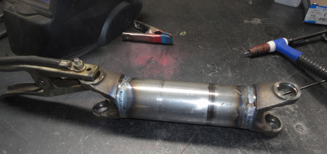
So after I had a flat face I added a piece of ¼ steel into the open space and machined it along with the stub to leave a nice little step to center the excellent bolt on yoke I found, I believe it fits Toyota driveshafts but now it fits Ford CV bodies!
The yoke has six 8mm blot holes and the holes do line up very well with the thick areas of the CV between where the balls were so I could drill and tap these for some high strength studs.
In the end I liked what I had done but did not really like the inner stub piece as the Cougar they came from had sat in somebody’s yard for years and there was a corroded area right where the seal contacted the axle, one side was worse than the other but I did not want to chance it and have an annoying little leak so I found a replacement set of axles ( pretty cheap too) and cut the inner stubs off.
It feels fairly strange to take a brand new axle half out of the bag and just lop the end off with a grinder and toss the rest, at least they were cheap.
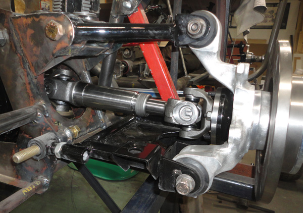
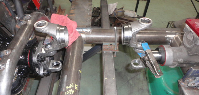
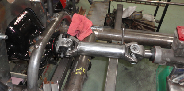
I machined the inners to fit the yokes and very carefully tig welded them together. The rest was fairly straight forward, assemble the U joints to the yoke parts slip the splines together and ta da! Axles! The best part was installing them; they fit like a glove and look great too!
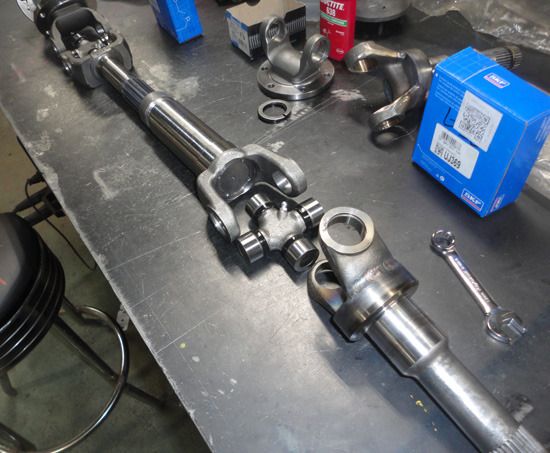 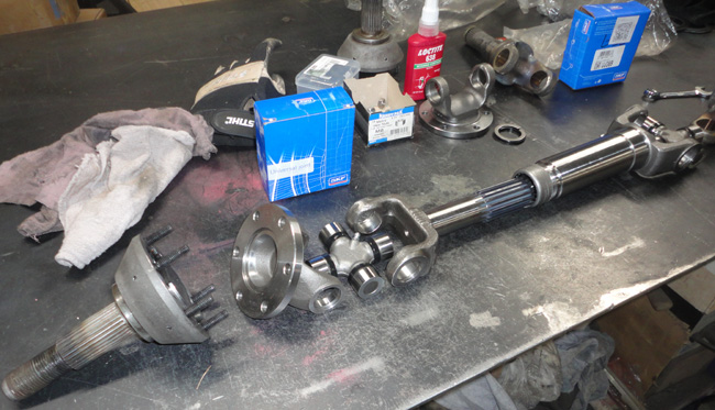 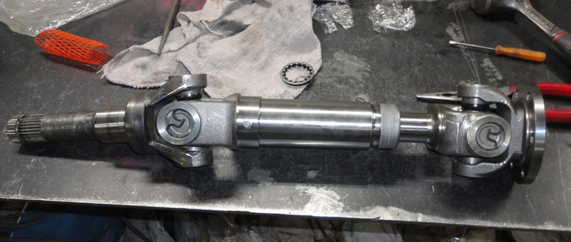
So while I was in the mood for yokes, U joints and welding I made up the drive shaft too. I cut the tube to length, squared up the ends on the handy old lathe, lined up the yokes and welded that together too. This also fits just fine and all that is left is a trip to the balancing shop for everything at some point in the future.
If nothing else I think an 8.8 can be used in an original style 289 chassis with very few changes and adapters can easily be made for original style axles too.
This all took a lot longer to do than to tell and was also not really done in one continuous process as things had to be figured out then parts had to be ordered and waited for too.
But I thought it best to edit it all into one timeline as I am still playing catch up with my posts.
I hope this meets with your approval Mr. MAP
Next time….out with the bad air…
All the best,
Hudson
.
__________________
Yes, I know,....... but it's mine you see.....
Perhaps he was always a shyster, but we just chose to over look it for awhile.
You build what you like and I will build what I like...it's all good
You know that guy,
The one in the neighborhood who likes to hang around the garage while you are working and talk about back when he had that killer 1977 Chevy Mustang
Last edited by old willy; 09-20-2023 at 11:34 AM..
|
09-19-2023, 04:59 AM
|
|
CC Member
|
|
|
Join Date: Mar 1999
Location: penn.,
Posts: 2,566
|
|
Not Ranked
part numbers for yokes and slips?
|
09-19-2023, 09:40 AM
|
|
CC Member
|
|
|
Join Date: Oct 2017
Location: Baysville,
Ont
Cobra Make, Engine: Mine, small block FORD
Posts: 360
|
|
Not Ranked
Hello Mr. Bruce,
No problem sir, I will post the numbers and great supplier I got them from when I get home tonight.
This was also surprisingly inexpensive compared to custom CV axles
I also believe I will have a question for you sir.
__________________
Yes, I know,....... but it's mine you see.....
Perhaps he was always a shyster, but we just chose to over look it for awhile.
You build what you like and I will build what I like...it's all good
You know that guy,
The one in the neighborhood who likes to hang around the garage while you are working and talk about back when he had that killer 1977 Chevy Mustang
|
09-19-2023, 07:01 PM
|
|
CC Member
|
|
|
Join Date: Oct 2017
Location: Baysville,
Ont
Cobra Make, Engine: Mine, small block FORD
Posts: 360
|
|
Not Ranked
Axle parts
Ok Bruce,
Here they are,
I ordered from an outfit called Driveshaft Parts at www.driveshaftparts.com they had what I was looking for, in stock, with options.
On some of things they seem to have their own house brand stuff as well as the big name brands.
Also they ship to Canada so that was good for me too. I do try and shop local but sadly Canada is a bit of a motorsports desert, perhaps it is our smaller population coupled with a shorter summer season but what it means is it harder and normally much more expensive to get the same items up here
I did take some of these numbers to the local parts store and went weak in the knees when he started giving me prices so driveshaftparts.com works for me.
BTW, up here in the frozen north I was taught that we don't have Speed shops, we have GREED shops....
OK, enough of my ranting
On the outboard end circular 6 bolt flange 2-2-1339
On the inboard end weld yoke 2-28-417
Outer axle male spline half 2-82-58X
Inner axle female spline half 2-3-5821KX
So obviously 2 of each of those and 4 1310 size U-joints plus your own cut up stock CV axles.
I think the original cars might have used 1330 size joints? but I am not sure. The donor Mustang power train was sporting 1310's on the driveshaft the 95 Cougar was 1330's but it was a tank! So I think these will be fine, we are not running any extreme angles either so that is what I went with.
Check out the website, they have all the specs there too to help you decide.
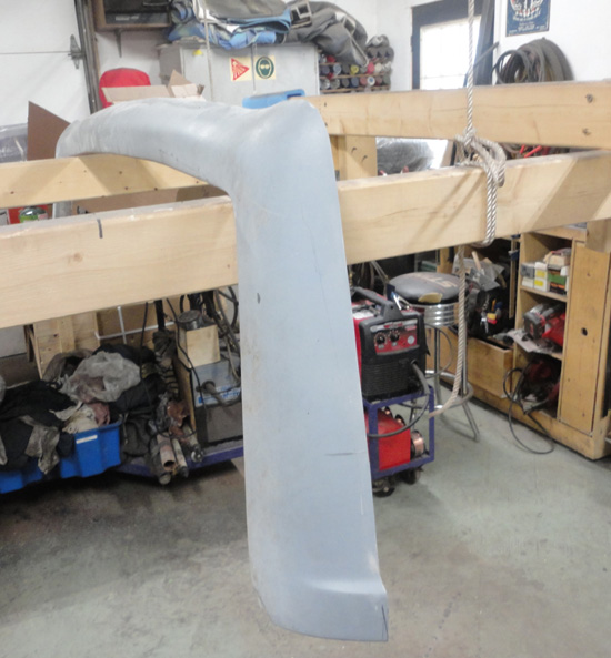
As for me, Mr. Bruce I am going to need a new hood or at least hood skin for my project, it has a nicely made but so wrong looking 427SC hood currently, I am looking for a regular no scoop hood skin as I intend on bonding it to a more correct looking tube frame. I could also be interested in a USRRC / FIA type if the smooth one is not available.
Can you help me?
Cheers,
Hudson
.
__________________
Yes, I know,....... but it's mine you see.....
Perhaps he was always a shyster, but we just chose to over look it for awhile.
You build what you like and I will build what I like...it's all good
You know that guy,
The one in the neighborhood who likes to hang around the garage while you are working and talk about back when he had that killer 1977 Chevy Mustang
Last edited by old willy; 09-19-2023 at 07:03 PM..
|
09-20-2023, 12:20 AM
|
|
CC Member
|
|
|
Join Date: Mar 1999
Location: penn.,
Posts: 2,566
|
|
Not Ranked
H man, thanks for the part no's. as for the hood(bonnet ), I have hoods with or without scoops, even got them with louvers, but, and this is the BIG but, iffin' you think the parts prices up there are bad, the shipping of a hood up your way is worse. if you want to investigate further , the box size is approxamately 48" X 50" X6", and weighs about 25lbs with the hood skin in it, thanks, b
|
 Posting Rules
|
You may not post new threads
You may not post replies
You may not post attachments
You may not edit your posts
HTML code is Off
|
|
|
All times are GMT -7. The time now is 01:40 AM.
Links monetized by VigLink
|


 Linear Mode


